


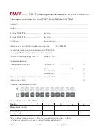


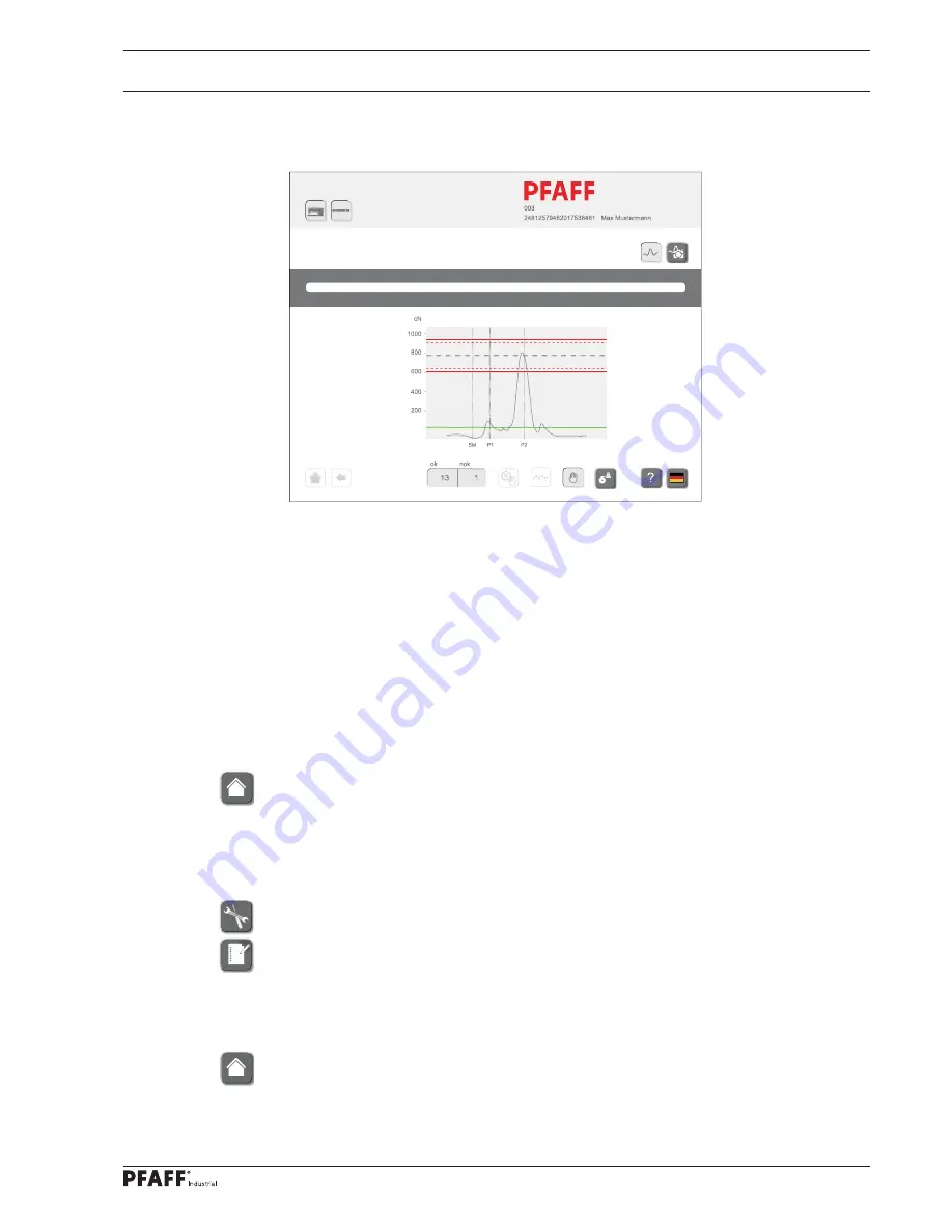
Calibration
123
●
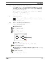
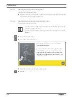
Switch on the monitor with function
1.
●
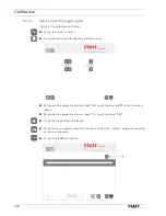
Carry out a test seam.
●
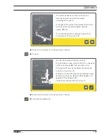
Check, whether the trigger signals with the largest hook loop and in t.d.c. take-up lever
are both in the maximum range of the thread strength signal.
●
If necessary alter the value for parameter
2011
(largest hook loop, standard value: “
344”)
accordingly.
●
If necessary alter the value for parameter
2013
(t.d.c. take-up lever, standard value: “
74”)
accordingly.
●
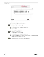
Carry out another test seam and check the altered value.
●
If necessary repeat the procedure until the setting for the trigger signals is correct.
●
Enter the values for the speed (
500
min-
1)
and for the parameters
2011
and
2013
in the
calibration certifi cate.
●
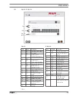
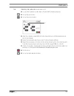
Call up the mode selection function.
5
.02.03
Check the zero position of the monitor power signal
(Item
3
of the calibration certifi cate)
●
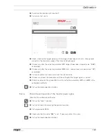
Call up the “tools” function.
●
Call up the menu for adjusting the parameter values.
●
Call up parameter
2010.
●
Check whether the value “
244”
is set. If necessary enter this value.
●
Call up the mode selection function.
Industrial
Summary of Contents for POWERLINE 3741
Page 1: ...296 12 19 008 002 Betriebsanleitung engl 06 12 DOKU SEAM SYSTEM 3741 3745 ...
Page 7: ...Register 01 ...
Page 8: ......
Page 14: ......
Page 15: ...Register 02 ...
Page 16: ......
Page 43: ...Register 03 ...
Page 44: ......
Page 81: ...Register 04 ...
Page 82: ......
Page 126: ......
Page 127: ...Register 05 ...
Page 128: ......
Page 129: ...Kalibrieranleitung engl 06 12 CALIBRATION INSTRUCTIONS 3741 3745 ...
Page 139: ...Register 06 ...
Page 140: ......
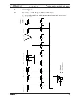
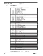
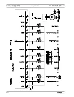
Page 147: ...135 91 191 528 95 Part 1 Version 12 01 12 Circut diagrams ...
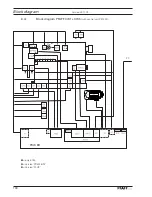
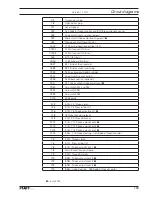
Page 148: ...136 Circut diagrams Version 12 01 12 91 191 528 95 Part 2 ...
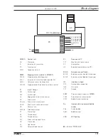
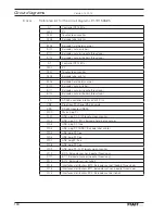
Page 149: ...137 91 191 528 95 Part 3 Version 12 01 12 Circut diagrams ...
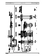
Page 150: ...138 Circut diagrams Version 12 01 12 91 191 528 95 Part 4 ...
Page 151: ...139 91 191 528 95 Part 5 Version 12 01 12 Circut diagrams ...
Page 152: ...140 Circut diagrams Version 12 01 12 91 191 528 95 Part 6 ...
Page 153: ...141 91 191 528 95 Part 7 Version 12 01 12 Circut diagrams ...
Page 154: ...142 Circut diagrams Version 05 01 12 91 191 536 95 ...
Page 155: ...143 91 191 536 95 Version 12 01 12 Circut diagrams ...