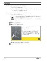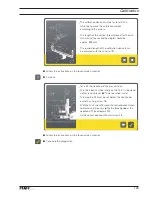
Calibration
127
5
.03
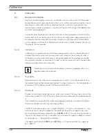
Checking the calibration
(calibration result)
●
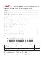
Carry out the calibration as described in Chapter
5.02
Calibration procedure.
●
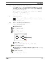
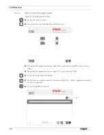
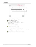
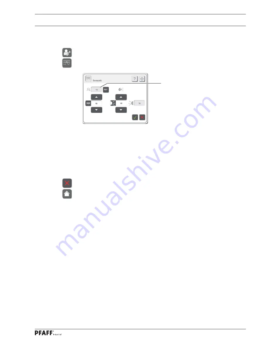
Call up the service menu.
●
Call up the sensor function.
●
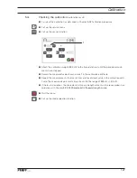
Attach the calibration weight (
500
cN) to the thread and wait until the pendulum move-
ments have stopped.
●
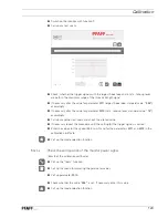
Record the measured value shown in box
1
in the calibration certifi cate.
●
Repeat the measurements four more times and record each value in the calibration certi-
fi cate. The measured value must always be within the range of
500
cN +/-
30
cN.
●
If there are deviations, the characteristic thread strength curve must be re-recorded in ac-
cordance with Chapter
5.02.05 Characteristic thread strength curve
.
●
Quit the menu.
●
Call up the mode selection function.
1
Summary of Contents for POWERLINE 3741
Page 1: ...296 12 19 008 002 Betriebsanleitung engl 06 12 DOKU SEAM SYSTEM 3741 3745 ...
Page 7: ...Register 01 ...
Page 8: ......
Page 14: ......
Page 15: ...Register 02 ...
Page 16: ......
Page 43: ...Register 03 ...
Page 44: ......
Page 81: ...Register 04 ...
Page 82: ......
Page 126: ......
Page 127: ...Register 05 ...
Page 128: ......
Page 129: ...Kalibrieranleitung engl 06 12 CALIBRATION INSTRUCTIONS 3741 3745 ...
Page 139: ...Register 06 ...
Page 140: ......
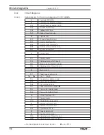
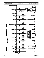
Page 147: ...135 91 191 528 95 Part 1 Version 12 01 12 Circut diagrams ...
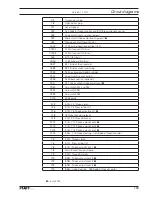
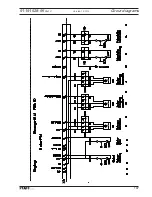
Page 148: ...136 Circut diagrams Version 12 01 12 91 191 528 95 Part 2 ...
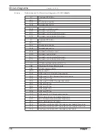
Page 149: ...137 91 191 528 95 Part 3 Version 12 01 12 Circut diagrams ...
Page 150: ...138 Circut diagrams Version 12 01 12 91 191 528 95 Part 4 ...
Page 151: ...139 91 191 528 95 Part 5 Version 12 01 12 Circut diagrams ...
Page 152: ...140 Circut diagrams Version 12 01 12 91 191 528 95 Part 6 ...
Page 153: ...141 91 191 528 95 Part 7 Version 12 01 12 Circut diagrams ...
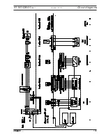
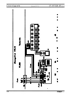
Page 154: ...142 Circut diagrams Version 05 01 12 91 191 536 95 ...
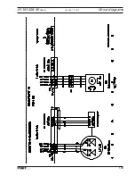
Page 155: ...143 91 191 536 95 Version 12 01 12 Circut diagrams ...

