


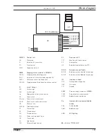


133
= only 3745
X
5
Output-input plug
X
6
Light barrier plug
X
11
not assigned
X
20
A20 bobbin thread monitor and B19 thread strength sensor
X
24
Knee switch seam section
(optional)
X
27
Knee switch stroke adjustment
(optional)
X
44
Stepping motor thread tension
XA
14
A14 Sewing head recognition (OTE)
XA
15.1
A15 Oil sensor (I2C-Bus)
XA
15.2
A15 Oil sensor (I2C-Bus) >
A
14
(OTE) (I2C-Bus)
XA
16
A16 Keyboard (I2C-Bus)
XB
31
B31 Initiator feed regulator
XB
33
B33 Initiator slider monitoring
XS
22
S22 Key electrical bobbin winder
XS24
Knee switch seam section
XS
26
S24 Seam section (optional)
XS27
S27 Knee switch stroke adjustment
XS
50
Cop switch S51 and S52
XS
51
Cop switch S51
XS
52
Cop switch S52
XL
10
Edge guide
XY
3
-909/..Y 3 Thread clamp
XY
4
-910/..Y 4 Presser foot lift
XY
6
-918/..Y 6 Stroke adjustment 1
XY
8
Y8 Thread tension release
XY
9
-900/..Y 9 Thread trimmer
XY
12
-918/..Y 12 Stroke adjustment 2
XY
13
-918/..Y 13 Stroke adjustment 3
XY
14
-918/..Y 14 Stroke adjustment 4
XY
15
-926/.. Y 15 Hook cleaning A20 Bobbin thread monitor
Y
3
-909/.. Thread clamp
Y
4
-910/.. Presser foot lift
Y
6
-918/.. Stroke adjustment 1
Y
8
Main thread tension release
Y
9
-900/.. Thread trimmer
Y
12
-
918/..
Stroke adjustment
2
Y
13
-
918/..
Stroke adjustment
3
Y
14
-
918/..
Stroke adjustment
4
Y
15
-
926/..
Hook cleaning A
20
Bobbin thread monitor
Version
12.01.12
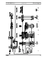
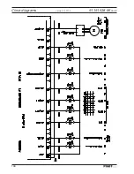
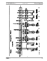
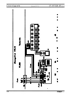
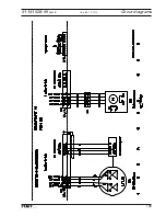
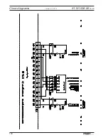
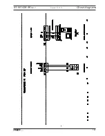
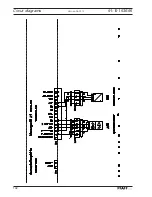
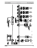
Circut diagrams
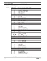
Summary of Contents for POWERLINE 3741
Page 1: ...296 12 19 008 002 Betriebsanleitung engl 06 12 DOKU SEAM SYSTEM 3741 3745 ...
Page 7: ...Register 01 ...
Page 8: ......
Page 14: ......
Page 15: ...Register 02 ...
Page 16: ......
Page 43: ...Register 03 ...
Page 44: ......
Page 81: ...Register 04 ...
Page 82: ......
Page 126: ......
Page 127: ...Register 05 ...
Page 128: ......
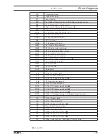
Page 129: ...Kalibrieranleitung engl 06 12 CALIBRATION INSTRUCTIONS 3741 3745 ...
Page 139: ...Register 06 ...
Page 140: ......
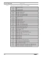
Page 147: ...135 91 191 528 95 Part 1 Version 12 01 12 Circut diagrams ...
Page 148: ...136 Circut diagrams Version 12 01 12 91 191 528 95 Part 2 ...
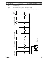
Page 149: ...137 91 191 528 95 Part 3 Version 12 01 12 Circut diagrams ...
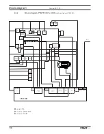
Page 150: ...138 Circut diagrams Version 12 01 12 91 191 528 95 Part 4 ...
Page 151: ...139 91 191 528 95 Part 5 Version 12 01 12 Circut diagrams ...
Page 152: ...140 Circut diagrams Version 12 01 12 91 191 528 95 Part 6 ...
Page 153: ...141 91 191 528 95 Part 7 Version 12 01 12 Circut diagrams ...
Page 154: ...142 Circut diagrams Version 05 01 12 91 191 536 95 ...
Page 155: ...143 91 191 536 95 Version 12 01 12 Circut diagrams ...