Input
22
Description of the functions
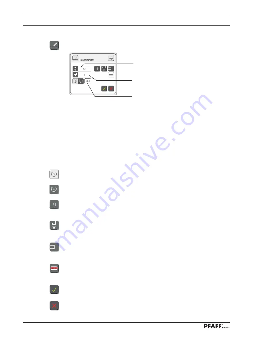
Stitch length input
After tapping area
1,
the input menu for the stitch length in the current seam sector is called
up.
Sewing foot lift input
After tapping area
2,
the input menu for the presser foot lift in the current seam sector is
called up.
Speed input
After tapping area
3
the input menu for the speed in the current seam sector is called up.
This function is used to select the variable speed. The speed can be adjusted with the pedal
position up to the maximum value (This function is activated in the example).
This function is used to select the constant speed. The speed cannot be adjusted with the
pedal position.
Needle raised at stop
This function is switched on or off for the current seam sector. If the function is switched on,
the needle moves to the top position when sewing stops.
Foot raised at stop
This function is switched on or off for the current seam sector. If the function is switched on,
the foot is raised when sewing stops.
Sew in label (only after a docu-seam area)
This function is switched on or off for the current seam sector. If the function is switched on,
a label is sewn in after the seam sector has been completed.
Scan label
This function is switched on or off for the current seam sector. If the function is switched on,
the label must be scanned.
Conclude the input
The input is concluded by taking over the selection and the entered values.
Stop the input
The input is concluded without taking over the selection and the entered values.
1
2
3
2
.04.01
Sewing parameter input
●
In seam programming call up the menu for sewing parameter input.
Summary of Contents for POWERLINE 3741
Page 1: ...296 12 19 008 002 Betriebsanleitung engl 06 12 DOKU SEAM SYSTEM 3741 3745 ...
Page 7: ...Register 01 ...
Page 8: ......
Page 14: ......
Page 15: ...Register 02 ...
Page 16: ......
Page 43: ...Register 03 ...
Page 44: ......
Page 81: ...Register 04 ...
Page 82: ......
Page 126: ......
Page 127: ...Register 05 ...
Page 128: ......
Page 129: ...Kalibrieranleitung engl 06 12 CALIBRATION INSTRUCTIONS 3741 3745 ...
Page 139: ...Register 06 ...
Page 140: ......
Page 147: ...135 91 191 528 95 Part 1 Version 12 01 12 Circut diagrams ...
Page 148: ...136 Circut diagrams Version 12 01 12 91 191 528 95 Part 2 ...
Page 149: ...137 91 191 528 95 Part 3 Version 12 01 12 Circut diagrams ...
Page 150: ...138 Circut diagrams Version 12 01 12 91 191 528 95 Part 4 ...
Page 151: ...139 91 191 528 95 Part 5 Version 12 01 12 Circut diagrams ...
Page 152: ...140 Circut diagrams Version 12 01 12 91 191 528 95 Part 6 ...
Page 153: ...141 91 191 528 95 Part 7 Version 12 01 12 Circut diagrams ...
Page 154: ...142 Circut diagrams Version 05 01 12 91 191 536 95 ...
Page 155: ...143 91 191 536 95 Version 12 01 12 Circut diagrams ...


