Adjustment
78
Fig. 4 - 02
4
.05.02
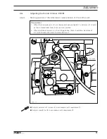
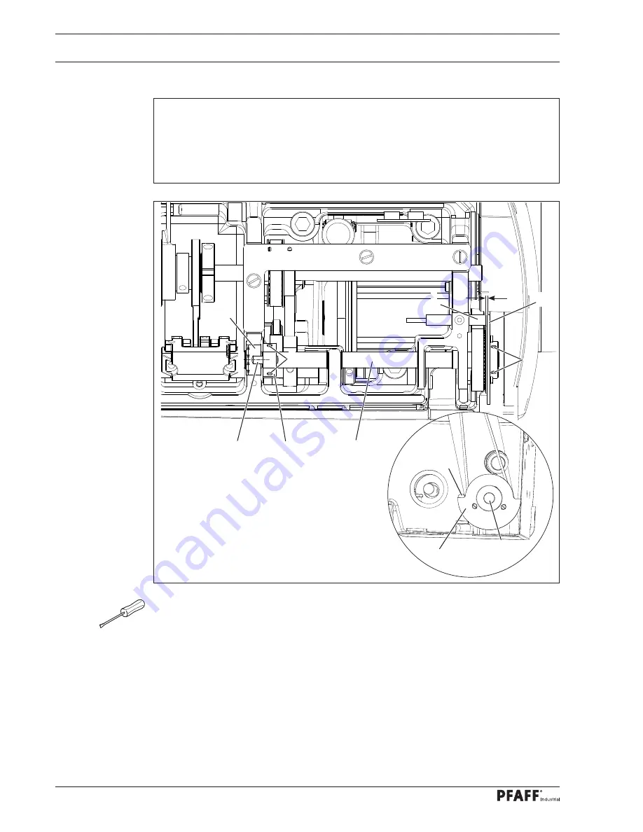
Zero position of the bottom and needle feed
Requirement
At stitch length setting "
0
"
1. turning the handwheel, the bottom transporter and the needle bar should not move, and
2. the bolt of lever
7
should be set to the middle position of recess
8
.
3. A gap of
0.3
mm
should exist between initiator
5
and switching plate
4
.
●
Turn machine on, stitch platen motor moves to reference position.
●
Turn shaft
1
of the stitch platen (screws
2
and
3
) in accordance with requirement
1
.
●
Move switching plate
4
in accordance with rule
3
and tighten screws
2
.
●
Set bolt
6
of lever
7
to the middle of recess
8
, and tighten screws
3
.
●
Check rule settings and adjust where required.
1
3
4
2
0,3 mm
5
4
1
5
X
=
X
6
7
8
Summary of Contents for POWERLINE 3741
Page 1: ...296 12 19 008 002 Betriebsanleitung engl 06 12 DOKU SEAM SYSTEM 3741 3745 ...
Page 7: ...Register 01 ...
Page 8: ......
Page 14: ......
Page 15: ...Register 02 ...
Page 16: ......
Page 43: ...Register 03 ...
Page 44: ......
Page 81: ...Register 04 ...
Page 82: ......
Page 126: ......
Page 127: ...Register 05 ...
Page 128: ......
Page 129: ...Kalibrieranleitung engl 06 12 CALIBRATION INSTRUCTIONS 3741 3745 ...
Page 139: ...Register 06 ...
Page 140: ......
Page 147: ...135 91 191 528 95 Part 1 Version 12 01 12 Circut diagrams ...
Page 148: ...136 Circut diagrams Version 12 01 12 91 191 528 95 Part 2 ...
Page 149: ...137 91 191 528 95 Part 3 Version 12 01 12 Circut diagrams ...
Page 150: ...138 Circut diagrams Version 12 01 12 91 191 528 95 Part 4 ...
Page 151: ...139 91 191 528 95 Part 5 Version 12 01 12 Circut diagrams ...
Page 152: ...140 Circut diagrams Version 12 01 12 91 191 528 95 Part 6 ...
Page 153: ...141 91 191 528 95 Part 7 Version 12 01 12 Circut diagrams ...
Page 154: ...142 Circut diagrams Version 05 01 12 91 191 536 95 ...
Page 155: ...143 91 191 536 95 Version 12 01 12 Circut diagrams ...


