background image


Datei/ file name:085501929k de-en-fr-it.docx 

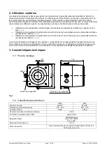
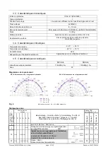
page 21 / 66 

 Drwg-no.: 30007-008-12k


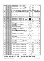
Individual combination of the tones for stages 1, 2, 3 and 4 (tone 32 of the Tone Selection Table) 


24 

ON  ON 


ON  ON 


Sirene / Siren / Sirène montante et descendante 


55 

23 

131 

26 

ON  ON  ON 


ON 


Sirene / Siren / Sirène montante et descendante 


         - Hoechst - 


100 

93 

31 

ON  ON  ON  ON  ON 


Sirene / Siren / Sirène montante et descendante 


    - NF C 48-265 


128 

54 

57 

32 


ON 

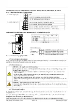
Auswahl der frei belegbaren Tonkombinationen in Stufe 2, 3 und 4 

– Programmierung s. unten/ 

Selection of the freely assignable tone combinations in stages 2, 3 and 4. For programming see below/ Sé-

lection des combinaisons de sons libres au niveau 2, 3 et 4. Programmation, voir ci-dessous


36 

ON  ON  ON 


Sirene / Siren / Sirène montante et descendante 


146 

67 

57 

45 


ON  ON 


Sirene / Siren / Sirène montante et descendante 


57 

93 

54 


ON  ON  ON 


Dauerton / Continuous tone / Son continu 

    1500 Hz 

57 

67 

55 


ON  ON 


ON 


Dauerton / Continuous tone / Son continu 

   1200 Hz 

88 

128 

57 


ON 


Dauerton / Continuous tone / Son continu 

  950 Hz 

128 

88 

60 


ON  ON 


Dauerton / Continuous tone / Son continu 

  825 Hz 

24 

93 

125 

63 


ON 


ON  ON 


Dauerton / Continuous tone / Son continu     - Bayer - 

  725 Hz 

97 

93 

67 


ON 


ON 


Dauerton / Continuous tone / Son continu 

  500 Hz 

24 

93 

125 

88 


ON 


ON 


Unterbrochener Ton / Interrupted tone /  
Son intermittent 


57 

128 

90 

ON 


Unterbrochener Ton / Interrupted tone /  
Son intermittent 


127 

108 

92 

ON 


ON 


Unterbrochener Ton / Interrupted tone /  
Son intermittent 


131 

146 

57 

93 


ON 


ON 


Hupe / Electromechanical horn /  
Trompe électro-mécanique 


128 

57 

97 

ON 


ON 


Unterbrochener Ton / Interrupted tone /  
Son intermittent 


63 

93 

98 


ON 


Notsignal Schweden / Swedish imminent danger si-
gnal / Son pulsé rapide 


      - SS 031711 - 


112 

128 

57 

100 

ON  ON  ON  ON 


Unterbrochener Ton / Interrupted tone /  
Son intermittent


57 

125 

108 


ON  ON  ON  ON 


Unterbrochener Ton / Interrupted tone /  
Son intermittent 


127 

60 

112 


ON 


Notsignal für Räumung/ Audible emergency evacua-
tion signal/ Signal international d‘évacuation  


        - ISO 8201 - 


57 

128 

116 

ON


ON


ON


Unterbrochener Ton / Interrupted tone / 
Son intermittent   

           - Schiff verlassen - 


117 

93 

125 

117 

ON


ON


Unterbrochener Ton / Interrupted tone /                       
Son intermittent    
(IMO SOLAS III/50 + SOLAS III/6.4) 

93 

116 

125 

125 

ON


ON


ON


Wechselton / Alternating tone / Modulation bi-ton 


57 

93 

24 

127 

ON


ON


Wechselton / Alternating tone / Modulation bi-ton 


90 

60 

128   


ON


ON


Wechselton / Alternating tone / Modulation bi-ton 


112 

57 

131 

ON


ON


ON


Wechselton / Alternating tone / Modulation bi-ton 


24 

55 

23 

142 

ON


ON


ON


Wechselton / Alternating tone / Modulation bi-ton 


54 

88 

146   


ON


ON


ON


Feueralarm Frankreich / French Fire sound / 
Son évacuation urgence                   - NFS32-001 - 


128 

67 

57 

Summary of Contents for 23106100601

Page 1: ...n Manual Safety Manual Instruction de service Manuel de s curit Istruzioni per l uso Manuale di sicurezza berwachter Schallgeber Monitored Sounder Sir ne surveill e Sirene controllate DS5 SIL DS10 SIL...

Page 2: ...sung gef hrlicher Zust nde 9 4 4 2 1 Verwendung als akustisches Warnsystem ohne Testfunktion 9 4 4 2 2 Verwendung als akustisches Warnsystem mit Testfunktion 10 4 5 Betriebsverhalten der berwachungsei...

Page 3: ...und Au eneinsatz geeigneten Schallgeber erzeugen Warnsig nale in 30 unterschiedlichen Tonarten die mit Hilfe eines internen Kodierschalters ausgew hlt werden k nnen Es besteht die M glichkeit optional...

Page 4: ...on durch eine bergeordnete Steuerung siehe Kapitel 4 4 2 1 Verwendung als Warnsystem mit automatischer Testfunktion durch eine bergeordnete Steuerung siehe Kapitel 4 4 2 2 Generell gilt dass die Betri...

Page 5: ...en DS10 SIL DS5 SIL Max Schallpegel 114 dB A 1m 108 dB A 1m Tonarten 30 Richtdiagramm Abb 4 Tonartentabelle Grundton Stufe 1 basic tone stage 1 Son de Base Kodierschalter DIP Switch Beschreibung Grund...

Page 6: ...ener Ton Interrupted tone Son intermittent 2 57 128 90 ON Unterbrochener Ton Interrupted tone Son intermittent 2 127 108 92 ON ON Unterbrochener Ton Interrupted tone Son intermittent 131 146 57 93 ON...

Page 7: ...onischer Systeme IEC61511 Funktionale Sicherheit Sicherheitstechnische Systeme f r die Prozessindustrie EN ISO 13849 1 in Anlehnung Sicherheitsbezogene Teile von Steuerungen Mit der Kennzeichnung des...

Page 8: ...n Zustand ein Diese Architektur wird schematisch in Abb 5 dargestellt Anlaufwarnungen und hnliche Anwendungen sind Architekturen die in der Regel dem High Demand Mode zuge ordnet werden k nnen Unmitte...

Page 9: ...fasst einen gef hrlichen Zustand und aktiviert das akustische Warnsys tem Output 3 b Die Diagnose 4 berwacht die Funktion des akustischen Warnsystems und meldet an ein bergeordnetes System 5 das OK c...

Page 10: ...ung SFF 99 0 99 1 99 1 99 1 99 1 99 1 DC 67 7 71 9 73 1 73 0 73 3 73 3 MTTR 48h h D Schallgeber 243 Fit S Schallgeber 79 Fit DU Diagnose 77 Fit S Diagnose 7459 Fit CCF 10 DU Gesamt 251 Fit S Gesamt 76...

Page 11: ...Werden Tonarten durch den Schallgeber selbstst ndig beendet wie z B bei den Tonarten 26 und 98 wird ebenfalls nach Ablauf einer Zeitdauer von 4 s ein Fehler gemeldet In diesem Fall muss die Steuerung...

Page 12: ...kann erfolgen Der Funktionstest kann hier Bestandteil der Anlaufwarnung sein Beide Teilsysteme der Schallgeberkanal und die berwachungsschaltung haben getrennte Versorgungsspannungs anschl sse Damit...

Page 13: ...rpr fen Die Person muss in der Lage sein das Warnsignal identifizieren zu k nnen Alternativ k nnen f r diesen Test geeignete technische Hilfsmittel verwendet werden Oszillogra fisch kann das Signal mi...

Page 14: ...h das Vorderteil abnehmen W hrend der Installa tion ist auf eine saubere und unbesch digte Dichtung zu achten i Die Anschlussbelegung wird im Kapitel 4 14 dargestellt j Die Kabelverschraubungen mit de...

Page 15: ...des H rverm gens zu verhindern bei Arbeiten Tests eine Schallschutzaus r stung tragen 4 17 Wartungshinweise Der Schallgeber erfordert keine besondere Wartung Es ist jedoch darauf zu achten dass das P...

Page 16: ...4 7 beschrie ben ist und auch beim Proof Test Kapitel 0 vorgenommen wird kann dabei sehr helfen Ist der Schallgeber defekt sollte die Instandsetzung im Herstellerwerk erfolgen F r den Austausch d rfen...

Page 17: ...ous statuses are detected 23 4 4 2 1 Use as acoustic warning system without test function 24 4 4 2 2 Use as acoustic warning system with test function 25 4 5 Operating behaviour of the monitoring equi...

Page 18: ...possibility of optionally switching to three other tones with external control Next to these factory settings the combination of tones can be freely arranged by on site programming The function of the...

Page 19: ...control see section 4 4 2 1 Use as a warning system with automatic test function via a superior control see section 4 4 2 2 In general the operational safety of the device and the therefore connected...

Page 20: ...S10 SIL DS5 SIL Max sound level 114 dB A 1m 108 dB A 1m Sound patterns 30 Sound level Fig 4 Tone selection table Grundton Stufe 1 basic tone stage 1 Son de Base DIP Switch Beschreibung Grundton Stufe...

Page 21: ...continu 500 Hz 24 93 125 88 ON ON Unterbrochener Ton Interrupted tone Son intermittent 2 57 128 90 ON Unterbrochener Ton Interrupted tone Son intermittent 2 127 108 92 ON ON Unterbrochener Ton Interr...

Page 22: ...es The DS SIL sounder fulfils the requirements of the functional safety according to IEC 61508 IEC 61511 4 2 Features The sounder described alone does not perform any protective function partial syste...

Page 23: ...EC EN61508 The safety loop is composed of a diagnosis channel with detection 4 evaluation of the hazardous state 2 and elements of the machine control system 5 for triggering the test function and for...

Page 24: ...4 2 2 the sounder partial systems output position 3 and diagnosis channel diagnosis position 4 are evaluated It should be noted that the sum of all PFH or PFD values must correspond to the required sa...

Page 25: ...espective measures in the fault message must be in accordance with the requirements of the function safety according to IEC EN61508 In the following a requirement rate less frequent than once a year i...

Page 26: ...ply If the capacity of failure has not become low resistance after this time then a fault has oc curred in the supply of the sounder channel in the sounder channel itself or in the monitoring equipmen...

Page 27: ...rm With the start up warning the function test must take place immediately before start up of the system that could lead to a hazard The function test may be part of the start up warning here Both par...

Page 28: ...n f Tone Acoustic check of the tone pattern of the locally used tone This can take place subjectively by trained personnel The pattern in tervals frequency response curve frequency change interval tim...

Page 29: ...rning devices directly next to one another as mutual influencing during simultaneous operation cannot be ruled out A distance of 1m fulfils the requirement h The front part can be removed by releasing...

Page 30: ...on TAS Schallgeber spannung Betriebs PE Terminal connections X1 PE 24V DC sounder operational voltage 0V DC sounder operational voltage Terminal connections X3 24V DC monitoring channel operational vo...

Page 31: ...s 4 18 Troubleshooting Despite high functional safety faults can occur during use These can have consequences in the sounder in the oper ational voltage supply or in the evaluation in the control syst...

Page 32: ...nt d tect es 39 4 4 2 1 Application comme syst me d alerte sonore sans fonction de test 41 4 4 2 2 Application comme syst me d alerte sonore avec fonction de test 41 4 5 Comportement en service du dis...

Page 33: ...La combinaison des sons qui est r gl e en usine peut gale ment tre programm e librement par le client Des versions sp ciales sont disponibles pour des conditions d utilisa tion particuli res La survei...

Page 34: ...esse se reporter au chapitre 4 4 2 1 Utilisation comme syst me d avertissement avec fonction de test automatique par une commande ma tresse se reporter au chapitre 4 4 2 2 La s curit d exploitation de...

Page 35: ...une utilisation l ext rieur 3 5 Caract ristiques acoustiques DS10 SIL DS5 SIL Intensit acoustique maximale 114 dB A 1m 108 dB A 1m Sons 30 Diagrammes de rayonnement Fig 4 Tableau des sons Grundton Stu...

Page 36: ...0 ON Unterbrochener Ton Interrupted tone Son intermittent 2 127 108 92 ON ON Unterbrochener Ton Interrupted tone Son intermittent 131 146 57 93 ON ON Hupe Electromechanical horn Trompe lectro m caniqu...

Page 37: ...Parties des syst mes de commande relatives la s curit La soci t Pfannenberg GmbH confirme avec le marquage CE de l appareil sa conformit aux exigences l gales des directives CE correspondantes La sir...

Page 38: ...nostic teste et surveille cette fonction et provoque l tat de s curit en cas de d faillance l aide d une boucle de s curit Cette architecture est repr sen t e sch matiquement par la Fig 5 Les avertiss...

Page 39: ...s curit constructive ou autres mesures ind pendantes de la volont pour atteindre l tat de s curit Le diagnostic peut uniquement tre pris en compte si le dispositif fait l objet d un test de fonctionn...

Page 40: ...no 30007 008 12k sonore sortie position 3 et le canal de diagnostic module de diagnostic position 4 Il convient d observer que face au syst me global la somme de toutes les valeurs PFH ou encore PFD d...

Page 41: ...te valuation est uniquement applicable pour des syst mes en Low Demand Mode La fonction de test d crite au chapitre 4 7 est prise en compte Celle ci doit n anmoins tre ex cut e de mani re automatique...

Page 42: ...signal sonore en tat exempt de d faillance implique la commande du relais MOS la sortie du relais MOS entre dans un tat faible imp dance avec une temporisation de 0 2 seconde Les conditions n cessair...

Page 43: ...plication Il est important pour le test du syst me que le changement de commutation du relais d alarme soit d tect en fonction de la g n ration du signal d avertissement acoustique Les intervalles req...

Page 44: ...s dangereux non d tect s automatiquement ainsi qu l appr ciation de l tat g n ral de l appareil La non ex cution des tests p riodiques selon la p riodicit requise en tra ne la perte du classement au n...

Page 45: ...te selon les r gles de l art en tenant compte de la r glementation et des directives applicables Les instructions de service et le manuel de s curit sont destin s au personnel autoris et quali fi en l...

Page 46: ...tion contre l inversion de polarit Pas de fonction en cas de l inversion de la polarit Fig 10 Affectation des broches et l ments de commande Affectation des bornes X1 PE 24V DC Tension de service sir...

Page 47: ...gr s form s en lectrotechnique Avant le montage veuillez d brancher tous les c bles d alimentation lectrique et veillez ce que le courant ne soit pas r tabli Assurez vous toujours de l absence de tens...

Page 48: ...galement effectu au Proof Test peut aussi tre tr s utile Si la sir ne est d fectueuse sa r paration devrait tre effectu e l usine du fabricant Les pi ces de rechange doi vent imp rativement tre des pi...

Page 49: ...zzo come sistema acustico di allarme senza funzione di test 57 4 4 2 2 Utilizzo come sistema acustico di allarme con funzione di test 58 4 5 Caratteristica operativa del dispositivo di sorveglianza 59...

Page 50: ...to all interno elettricamente e acusticamente da un canale di diagnosi L emissione di un segnale acustico di allarme accompagnata dall attivazione di un rel MOS Questa informazione pu essere valutata...

Page 51: ...dell apparecchio e dunque del sistema connesso garantita solo se ci si attiene all utilizzo conforme alle disposizioni come da istruzioni per l uso Pericoli specifici dell applicazione possono risulta...

Page 52: ...imatici Temperatura di esercizio 25 C 55 C Temperatura stoccaggio 40 C 70 C Umidit relativa 90 Ideale per impiego all aperto Ideale per impiego all aperto 3 5 Dati acustici DS10 SIL DS5 SIL Intensit s...

Page 53: ...ON ON Suono continuo Bayer 725 Hz 2 97 93 67 ON ON Suono continuo 500 Hz 24 93 125 88 ON ON Suono intermittente 2 57 128 90 ON Suono intermittente 2 127 108 92 ON ON Suono intermittente 131 146 57 93...

Page 54: ...bili IEC61511 Sicurezza funzionale Sistemi di sicurezza per l industria di trasformazione EN ISO 13849 1 in conformit Parti di sicurezza di dispositivi di controllo L apparecchio contrassegnato dal ma...

Page 55: ...ntazione schematica della suddetta architettura Le segnalazioni di avviamento e simili applicazioni sono architetture che di norma possono essere attribuite alla high demand mode Prima della messa in...

Page 56: ...presa in considerazione unicamente se l apparecchio fa parte di un test di funzionamento periodico e automatico il cui intervallo minimo deve corrispondere secondo la norma IEC EN61508 a circa 10 100...

Page 57: ...riodico proof test Il proof test descritto nel capitolo 4 10 delle istruzioni per l uso del manuale di sicurezza In questo caso per calcolare il PFD per intervalli diversi del Proof Test sufficiente m...

Page 58: ...frequente di una volta all anno low demand Intervallo di test auto matico mensile 672h settimanale 168h giornaliero 24h mensile 672h settimanale 168h giornaliero 24h Intervallo tra test 1 1 1 15 15 1...

Page 59: ...sti gi a bassa impedenza possibile che ci sia un cortocircuito tra conduttori o un malfunzionamento del circuito di sorveglianza b Disinserendo la tensione operativa del canale della sirena il rel di...

Page 60: ...so di avvio Entrambi i sistemi parziali vale a dire il canale della sirena e il circuito di monitoraggio presentano connessioni di ten sione di alimentazione separate In questo modo possibile un contr...

Page 61: ...assa al dissipa tore di calore del circuito di commutazione U3 livello TTL g Tipo di suono op zione TAS Poich utilizzata l opzione Selezione esterna del tipo di suono neces sario ripetere il passaggio...

Page 62: ...are le 4 viti Durante l installazione assicurarsi che la tenuta sia pulita e priva di danni i Per l assegnazione delle connessioni vedere capitolo 4 14 j I passacavi di cui dotato il dispositivo sono...

Page 63: ...orsetto X3 24V CC tensione d esercizio canale di sorveglianza 0V CC tensione d esercizio canale di sorveglianza Contatto di allarme IN a potenziale zero rel MOS 230 V 80 mA Contatto di allarme OUT a p...

Page 64: ...elettrici Prima del montaggio togliere tensione a tutte le linee in ingresso e metterle in sicurezza in modo che non possano riattivarsi Accertarsi sempre che non ci sia tensione possibile riattivare...

Page 65: ...el proof test di cui al capitolo 4 10 pu essere molto utile Una eventuale sirena difettosa deve essere fatta riparare presso il produttore I ricambi utilizzati devono essere asso lutamente originali E...

Page 66: ...er Serial Number N de s rie Numero di serie Lieferdatum Date of Delivery Date de livraison Data di consegna 5 Gew hrleistungszeit Warranty time Dur e de la garantie Durante della garanzia ZVEI 12 Mona...

Reviews: