background image


Operating instructions CWB-ATEX 


120799 61 616 07 300 0 

05/2021 

Page 13 / 14 

30046-005k


en 

10.2  Opening and closing of Ex d housing 


DANGER


Explosion hazard due to incorrect maintenance! 
Non-compliance results in severe or fatal injuries to persons. 

•  Disconnect all supply lines from mains! 
•  Corroded flameproof Ex-joint must not be cleaned with abrasives 

or wire brushes and may only be cleaned chemically, e.g. with 
reducing oils from ESSO, type Vassol or similar. 

•  To avoid corrosion, the flameproof Ex-joint must be treated regu-

larly with acid

–free grease that is compatible with aluminium. 

Apply water-repellent, thermally stable and chemically inert 
greases exclusively whose drop point is at least 80°C. Corrosion 
protection by coating with paint is fundamentally forbidden! 


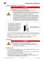
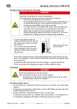
•  To open the pressure-proof en-

closed optical beacon first undo the 
M4 locking screw fitted at the side. 
(see sketch). 

•  Then unscrew the polycarbonate 

hood embedded in the housing by 
turning it to the left (about seven 
thread turns). 


Safety screw with hexa-
gon socket M4 


•  Closing the housing: Observe caution when fitting the housing and turn it to the 

stop 

– it is imperative to ensure that the flameproof thread is not damaged (explo-

sion protection)! 

•  At least five load-bearing thread turns must engage – explosion protection! 
•  Firmly screw down the locking screw again to protect against turning! 

10.3  Repair 


DANGER


Explosion hazard due to improper repair! 
Non-compliance results in severe or fatal injuries!  

•  Repair work on the devices must be performed only by the manu-

facturing plant, contact see Chapter 1. 

10.4  Returning the device 

•  Customer service is available for returns for repairs or servicing, see contact data, 

chapter 1. 

•  Provide an exact description of the defect and the SRO (RMA) numbers specified 

by Pfannenberg with the device. 

•  Include a reference document (delivery note or invoice copy). 
•  Forward the cooling unit to us, complete with all accessories, in the original box or 

in comparable packaging with freight and transport insurance pre-paid. 


Summary of Contents for CWB-ATEX

Page 1: ...ion 5 5 Technische Daten 6 6 Transport und Lagerung 8 7 Montage und Installation 8 Ma angaben Befestigungsma e 8 7 1 1 Ma zeichnungen 8 7 1 2 Montagezubeh r 8 7 1 3 Zubeh r 9 7 2 Montage Demontage Geb...

Page 2: ...e Beratung unter der Rufnummer 49 0 40 73412 0 1 1 Angaben zur Betriebsanleitung Diese Betriebsanleitung liefert wichtige Sicherheitsinformationen zum Schutz vor Gefahren Die Digitale Be triebsanleitu...

Page 3: ...e folgt aufgebaut Signalwort GEFAHR WARNUNG VORSICHT HINWEIS Art und Quelle der Gefahr des Schadens Folgen der Gefahr Ergreifen von Gegenma nahmen zum Vermeiden der Gefahr bzw des Schadens GEFAHR Gefa...

Page 4: ...und nur f r den zugelassenen Einsatzzweck ver wenden F r Sch den die durch fehlerhaften oder unzul ssigen Einsatz des Ger ts sowie durch Nichtbeachtung dieser Betriebsanleitung entstehen besteht kein...

Page 5: ...entfremdete Verwendung Nichtbeachten f hrt zu schweren oder t dlichen Verletzungen Ger t nur entsprechend den in dieser Betriebsanleitung festge legten Betriebsbedingungen verwenden Ger t nur entsprec...

Page 6: ...0 ATEX 1 222 X DNV GL TAA00002GU Elektrische Kenndaten CWB ATEX Bemessungsspannungs bereich Bemessungsstromaufnahme 12 V 48 V DC 0 Hz 24 V 42 V AC 50 60 Hz 0 3 0 5 A 60 V 80 V DC 42 V 48 V AC 50 60 Hz...

Page 7: ...eh r bestellbar Befestigungsteile Edelstahl Dichtring NBR O Ringdichtung Sonderverschluss Ex d Geh use M4 Stiftschraube mit Innen sechskant Montage Installation Leitungs einf hrungen 1 x M20 x 1 5 Ver...

Page 8: ...nicht st rzen 7 Montage und Installation Ma angaben Befestigungsma e 7 1 1 Ma zeichnungen alle Ma e in mm Zoll nderungen vorbehalten 7 1 2 Montagezubeh r Montagezubeh r aus Edelstahl komplett mit Befe...

Page 9: ...tage Gebrauchslage GEFAHR Explosionsgefahr durch unzureichend gesch tztes Ger t Nichtbeachten f hrt zu schweren oder t dlichen Verletzungen Ger t an einem Ort der vor mechanischen Einfl ssen sicher is...

Page 10: ...hern Elektrischer Anschluss Die Klemmung exakt durchf hren Keine Isolierung des Leiters unterklemmen Die Leiter nicht vertauschen Die Regeln der Technik bei Anschluss des Leiters beachten Die Leiter f...

Page 11: ...en und Verschlussstopfen fest angezogen sind Kontrollieren ob alle Leiter fest angeklemmt sind Kontrollieren ob Netzspannung mit der Bemessungsbetriebsspannung berein stimmt Kontrollieren ob die f r d...

Page 12: ...geltenden nationalen Bestimmungen im Einsatzland beachten Bei der Instandhaltung Wartung des Ger ts mindestens folgende Punkte pr fen fester Sitz der untergeklemmten Leitungen Rissbildung und andere s...

Page 13: ...gs schraube M4 l sen siehe Skizze Danach die in dem Geh use ein gebettete Polycarbonat Haube durch Linksdrehung etwa 7 Ge windeg nge abschrauben Sicherungsschraube mit Innensechskant M4 Zum Verschlie...

Page 14: ...en 12 Entsorgung Nationale und lokal g ltige Vorschriften und gesetzliche Bestimmungen zur Ent sorgung beachten Materialien getrennt dem Recycling zuf hren Umweltgerechte Entsorgung aller Bauteile gem...

Page 15: ...echnical Data 6 6 Transport and storage 8 7 Mounting and installation 8 7 1 Dimensions fastening dimensions 8 7 1 1 Dimensional drawing 8 7 1 2 Mounting accessories 8 7 1 3 Accessories 9 7 2 Mounting...

Page 16: ...chnical support on 49 0 40 73412 0 1 1 Information regarding the operating instructions These operating instructions provide important safety information for protection against hazards The digital ope...

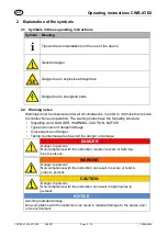
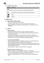
Page 17: ...notes have the following structure Signalling word DANGER WARNING CAUTION NOTICE Type and source of danger damage Consequences of danger Taking countermeasures to avoid the danger or damage DANGER Da...

Page 18: ...e device in accordance with its intended and approved purpose only We cannot be held liable for damage to the device caused by incorrect or unau thorised use or non compliance with these operating ins...

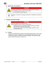
Page 19: ...design DANGER Explosion hazard due to improper use Non compliance results in severe or fatal injuries Use the device only in accordance with the operating conditions described in these operating instr...

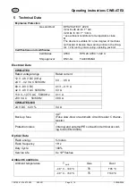
Page 20: ...val ATEX EPS 20 ATEX 1 222 X DNV GL TAA00002GU Electrical Data CWB ATEX Rated voltage range Rated current 12 V 48 V DC 0 Hz 24 V 42 V AC 50 60 Hz 0 3 0 5 A 60 V 80 V DC 42 V 48 V AC 50 60 Hz 0 13 0 11...

Page 21: ...ess steel accessory Fixing elements stainless steel Sealing ring NBR O ring seal Special lock Ex d enclosure M4 hexagon socket stud Mounting Installation Cable entries 1 x M20 x 1 5 stopping plug 1 x...

Page 22: ...rop the device 7 Mounting and installation 7 1 Dimensions fastening dimensions 7 1 1 Dimensional drawing all dimensions in mm inches Subject to change 7 1 2 Mounting accessories Mounting accessories m...

Page 23: ...unting operating position DANGER Explosion hazard due to inadequately protected device Non compliance results in severe or fatal injuries The device must be mounted protected against impact Alternativ...

Page 24: ...tions against unauthorized switching Electrical Connection Clamping must be carried out precisely Do not clamp any part of the conductor insulation Do not interchange the conductors Observe the techni...

Page 25: ...able entries and stopping plugs have been tightened firm ly Check if all conductors have been clamped firmly Check if the line voltage and the rated operational voltage are consistent Check if the per...

Page 26: ...ccording to IEC 60079 17 and IEC 60079 19 i Observe the relevant national regulations in the country of use The following tests and measures must be carried out during regular maintenance if the condu...

Page 27: ...lycarbonate hood embedded in the housing by turning it to the left about seven thread turns Safety screw with hexa gon socket M4 Closing the housing Observe caution when fitting the housing and turn i...

Page 28: ...ve national and local regulations and statutory regulation regarding disposal Separate materials when sending it for recycling Ensure environmentally friendly disposal of all components according to t...

Page 29: ...ues techniques 6 6 Transport et stockage 8 7 Montage et installation 8 7 1 Cotes cotes de fixation 8 7 1 1 Plan d encombrement 8 7 1 2 Accessoires de montage 8 7 1 3 Accessoires 9 7 2 Montage d montag...

Page 30: ...ers techniques au num ro suivant 49 0 40 73412 0 1 1 Informations concernant le mode d emploi Le pr sent document contient des informations de s curit importantes pour se prot ger contre les dangers L...

Page 31: ...nt sont structur es de la mani re suivante Mots d avertissement DANGER AVERTISSEMENT ATTENTION AVIS Type de danger dommage et origine Cons quences du danger Prise de mesures de correction pour viter l...

Page 32: ...dispositions et pour l appli cation pour laquelle il est pr vu Nous ne saurions tre tenus pour responsables de dommages r sultant d une uti lisation erron e ou non autoris e du dispositif ou du non re...

Page 33: ...ure du dispositif DANGER Risque d explosion r sultant d une utilisation non conforme l emploi pr vu Des blessures graves ou mortelles peuvent r sulter du non res pect de cette consigne N utiliser le d...

Page 34: ...X DNV GL TAA00002GU Caract ristiques lectriques CWB ATEX Plage de tensions assign es Consommation de courant assign e 12 V 48 V CC 0 Hz 24 V 42 V CA 50 60 Hz 0 3 0 5 A 60 V 80 V CC 42 V 48 V CA 50 60...

Page 35: ...e command comme accessoire Pi ces de fixation Fil d acier inoxydable Bague d tanch it Joint torique NBR Fermeture sp ciale Bo tier Ex d vis 6 pans M 4 Montage Installation Presse toupes 1 x M20 x 1 5...

Page 36: ...et installation 7 1 Cotes cotes de fixation 7 1 1 Plan d encombrement Toutes les dimensions sont en mm pouces Sous r serve de modifications 7 1 2 Accessoires de montage Accessoires de montage en acier...

Page 37: ...ilisation DANGER Risque d explosion en cas d appareil insuffisamment prot g Le non respect de l instruction entra ne des blessures graves ou mortelles Monter l appareil un endroit prot g contre les in...

Page 38: ...ue Le serrage doit tre effectu tr s soigneusement Veiller ne pas serrer une partie de l isolation du conducteur sous la borne Ne pas inverser les conducteurs Lors du branchement du conducteur respecte...

Page 39: ...sse toupes et bouchons obturateurs sont bien serr s V rifier si tous les conducteurs sont serr s fermement V rifier si la tension d alimentation est conforme la tension assign e d emploi V rifier si l...

Page 40: ...ion conform ment la norme CIE 60079 17 et CIE 60079 19 i Observer galement les r glementations en vigueur dans le pays d utilisation Les contr les et mesures suivants doivent tre effectu s dans le cad...

Page 41: ...voir croquis D visser ensuite le capot en poly carbonate int gr dans le bo tier en tournant vers la gauche 7 filets environ Vis de blocage six pans creux M4 Pour fermer positionner avec pr caution le...

Page 42: ...insi que les dispositions l gales relatives l limination Les mat riaux doivent tre recycl s s par ment S assurer d une limination de tous les composants respectueux de l environne ment conform ment au...

Reviews: