685408014B
12
The condensate is discharged in the following way:
•In case of normal condensate drainage a reservoir
(option) collects the condensate which is then drained by
means of a hose.
Always ensure that the condensate is drained properly
(safety- drainage).
Excessive condensation can occur if, for example, the
switch cabinet is not sealed or if the internal temperature
of the switch cabinet is frequently below the dew point.
Caution
Please check the sealing of the switch cabinet, if there is
excessive condensate during the normal operation.
In order to prevent the excessive condensate so we
recommend to installed a door contact switch. It will
switch off the cooling unit when the switch cabinet door is
opened.
8 Installations
8.1 General
•In order to keep the cabinet‘s proper ventilation, it is
important to select the correct installation place for the
cooling unit.
•It must be keep the distance at 200mm at least for the
single units or the unit and the wall.
•The cooling unit‘s electrical connection terminal to be
reserved at least 40mm space and the electrical
components shall not impede air circulation in the internal
cabinet.
•It must be switch off the power supply when the cooling
unit installed.
•The site of installation must be protected against
contamination.
Caution:
If the cooling unit is mounted on an switch cabinet door, it
must be confirmed that hinges can support the additional
weight or that the switch cabinet will not topple over when
the door‟s opened.
Caution:
Chips may damage the switch cabinet
.
It must be use a cover sheet to void the sward enter into
the cabinet to damage the electrical components when
you are installing a hole in the installation site.
Hint
To facilitate installation with heavy units, M8 lifting eyes
can be screwed into the upper fixing on the equipment
housing. Simple‟‟ one man installation‟‟ is thereby
possible.
8.2 Installation work
The mounting surface of the switch cabinet is to be
provided with cutout(s) and holes for air ventilation
openings and for securing the unit according to the
accompanying sheet.
The drawing on the accompanying sheet also shows the
location of the electrical connections and ventilation
openings.
1) If the cabinet is not reserved for the opening hole of the
cooling unit, please cut-out on the cabinet (refer to the
drawing on accompany sheet), then remove burrs from
the cut edge.
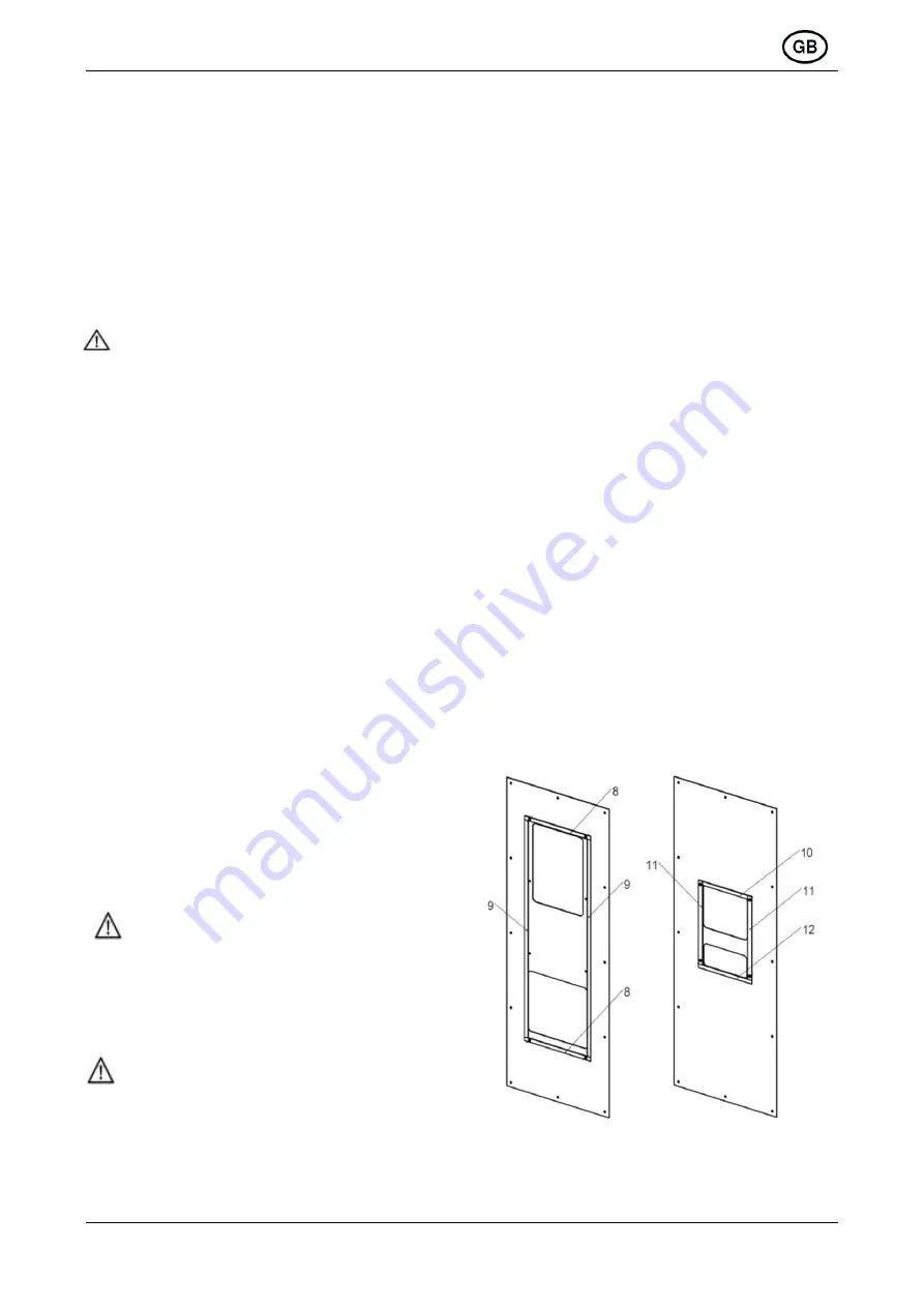
2) Please take out sealing strips (Pos.8, 9 or 10, 11, 12)
on the outside of the cabinet, make sure the hole of
sealing strip 8 or 11 concentric with switch cabinet, the
sealing strip 9 or 10 & 12 and 8 or 11 align at outside line,
then paste sealing strip on the swith cabinet.
3) Please take out the
thread rod, flat gasket, spring
washer, nut and bolt (Pos. 3, 4, 5, 6, 7) on the inside of the
cabinet and lock the cooling unit tightly.
4) Feeding the condensate run-off tube through the
opening in the base of the unit. Lay the tube with a
downward fall. Shorten as required.

