685408014B
14
measured by temperature sensor.The cooling unit can be
set at different internal temperature through operating
console display, (See attached table) the system will
Disallowed when exceeds the limit temperature.
The cooling unit has the function of power-on self-test, the
run-time real-time monitoring. The cooling unit will
generate an alarm when there is a failure during power-on
self-test.
Caution:
The cooling unit can only run in the case
of installing the front cover, otherwise it will be damaged
by poor heat dissipation.
10.2 Operate the display
The cooling unit is provided with an operation display.
―0.0
℃
‖ is displayed for 3s after the supply power is
switched on, then internal temperature is shown. This
indicates the unit works properly. If there is a failure or an
alarm, the operation display‘s alarm lamp will be light and
accompanied by an alarm sound, which makes it easier to
diagnose the cooling unit. (Refer to section 14)
10.3 Start-up / Test mode
The cooling unit will can
‘t work If on front of get supply
power the door switch is open, The test mode is basically
activated after renewed connection of the supply voltage
and is independent of the instantaneous ambient
conditions when the door contact is closed.First of all the
unit runs though a start-up mode lasting 30 seconds
which is followed by a test mode lasting 110 seconds. The
unit will still running when there is an alarm during the test
mode. After finishing the test mode, if have alarms, show
the alarm code in the panel, must take off the alarm, it can
enter into a normal working mode if there is no failure.
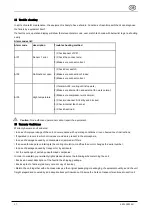
10.4 Unit characteristics
Mode
Time curve
Characteristics
Start-up
mode
t=0s-3s
t=3s-30s
No function
,
Operation
display
shows ‗‘0.0
℃
‘‘
Shows internal
temperature
Test mode
t=30s-40s
t=40s-50s
t=50s-80s
t=80s-140s
Internal fan start up;
External fan start up
Internal fan stop;
Compressor start up
External fan stop;
Internal fan, external
fan, compressor all
start up.
10.5 Door contact
For safety reasons, a door limit switch should be
connected to the terminals provided on the cooling unit.
(see the wiring diagram on housing cover or supplement).
With the switch in place, when enclosure door is opened
(thereby opening the switch), all of the motors are turned
off with a time lag.
10.6 Equipment fault
Failure contact X54
—1,2pin is NC, it close when power
supply without alarm, a fault in the cooling unit will cause
the breaking and show the alarm code. (See Section 14).
10.7 Self-check function
The cooling unit has functions of power-on self-check, and
real-time self-check.
Power-on self-check function is power-on testing mode.
(see Sections 10.3&10.4)
Real-time self-check function allows the cooling unit
monitoring if there is an abnormal occurrence during
operation and reporting timely.
10.8 Setting possibilities
By means of operation display, different cabinet
temperature as well as parameters can be selected. (see
Section 11)
Attention:
Changes to the operating parameters
of the cooling unit should only be made by authorized
personnel.
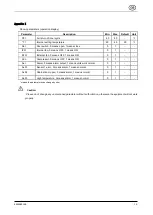
11 Parameters View and Settings
Parameters of cooling unit can be monitored and set by
operation display.
•Cooling unit control system includes master control board,
operation panel.

