background image

24

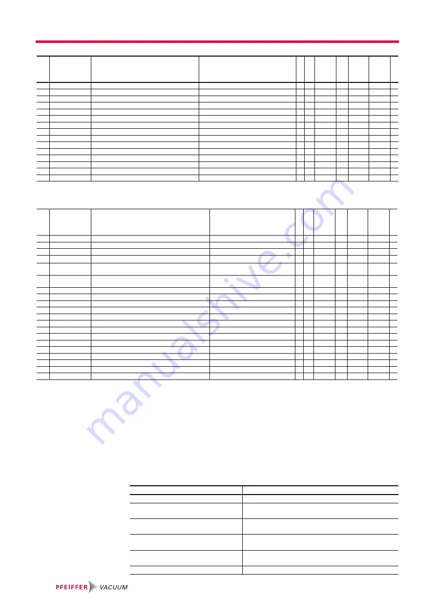
The Pfeiffer Vacuum parameter set

9.2.5

Set value settings

9.3

Configuring the connections

The electronic drive unit is pre-configured in the factory. Thereby the turbopump is im-
mediately operational with the necessary functions. The connections of the electronic 
drive unit can be configured to suit individual requirements using the parameter set.

9.3.1

Accessory connection

Configuration via parameter 

[P:035]

[P:036]

or 

[P:038]

.

349 ElecName

Name of electronic drive unit

4 R

354 HW Version

Hardware version electronic drive unit

4 R

360 ErrHist1

Error code history, pos. 1

4 R

x

361 ErrHist2

Error code history, pos. 2

4 R

x

362 ErrHist3

Error code history, pos. 3

4 R

x

363 ErrHist4

Error code history, pos. 4

4 R

x

364 ErrHist5

Error code history, pos. 5

4 R

x

365 ErrHist6

Error code history, pos. 6

4 R

x

366 ErrHist7

Error code history, pos. 7

4 R

x

367 ErrHist8

Error code history, pos. 8

4 R

x

368 ErrHist9

Error code history, pos. 9

4 R

x

369 ErrHist10

Error code history, pos. 10

4 R

x

397 SetRotSpd

Set rotation speed (rpm)

1 R

rpm

0

999999

398 ActualSpd

Actual rotation speed (rpm)

1 R

rpm

0

999999

399 NominalSpd

Nominal rotation speed (rpm)

1 R

rpm

0

999999

#

Display

Designation

Functions

Dat

a

 t

yp

e

Acc

ess

  Unit

min max

default

#

Display

Designation

Functions

Da

ta

 ty

pe

Ac

ce

ss 

Unit

min max

default

700 RUTimeSVal

Set value run-up time

1 RW min

1

120

12

x

701 SpdSwPt1

Rotation speed switchpoint 1

1 RW %

50

97

80

x

707 SpdSVal

Set value in rot. speed setting mode

2 RW %

50

100

65

x

708 PwrSVal

Set value power consumption

7 RW %

10

100

100

1

x

710 Swoff BKP

Switching off threshold backing pump in intermittend 

mode

1 RW W

0

1000

0

x

711 SwOn BKP

Switching on threshold backing pump in intermittend 

mode

1 RW W

0

1000

0

x

717 StdbySVal

Set value rotation speed at standby

2 RW %

20

100

66.7

x

719 SpdSwPt2

Rotation speed switchpoint 2

1 RW %

5

97

20

x

720 VentSpd

Venting rot. speed at delayed venting

7 RW %

40

98

50

x

721 VentTime

Venting time at delayed venting

1 RW s

6

3600

3600

x

730 PrsSwPt 1

Pressure switchpoint 1

10 RW hPa

x

732 PrsSwPt 2

Pressure switchpoint 2

10 RW hPa

x

739 PrsSn1Name

Name sensor 1

4 R

740 Pressure 1

Pressure value 1

10 RW hPa

x

742 PrsCorrPi 1

Correction factor 1

2 RW

x

749 PrsSn2Name

Name sensor 2

4 R

750 Pressure 2

Pressure value 2

10 RW hPa

x

752 PrsCorrPi 2

Correction factor 2

2 RW

x

777 NomSpdConf

Nominal rotation speed confirmation

1 RW Hz

0

1500

0

x

797 RS485Adr

RS-485 device address

1 RW

1

255

1

x

1. depending on the pump type

Option

Description

0 = Fan (continous operation)

Control via parameter Pumping station

1 = Venting valve, normally closed

Control via parameter Enable venting, when using a venting 
valve which is normally closed.

2 = Heating

Control via parameters Heating and Rotation speed switch-
pont attained

3 = Backing pump

Control via parameters Pumping station and  operation 
mode backing pump

4 = Fan (temperature controlled)

Control via parameter Pumping station and temperature 
thresholds

5 = Sealing gas

Control via parameters Pumping station and Sealing gas

Summary of Contents for PM C01 870

Page 1: ...PT 0454 BEN B 1603 OPERATING INSTRUCTIONS EN Translation of the original instructions TCP 1200 Electronic Drive Unit...

Page 2: ...lation 12 5 2 Connection external pump 12 5 3 Earthing 13 5 4 Connecting to the mains power supply 13 6 Connection remote 15 6 1 Pin assignment 15 6 2 Operation via remote connection 15 6 2 1 24 V DC...

Page 3: ...peration with accessories 31 9 4 12 Vent modes 31 9 4 13 Monitoring the thermal load 32 9 5 Switching on off the pump 32 9 5 1 Switching on 32 9 5 2 Switching off 32 10 Operation 33 10 1 Function 33 1...

Page 4: ...ns The safety instructions in Pfeiffer Vacuum operating instructions are the result of risk evaluations and hazard analyses and are oriented on international certification stan dards as specified by U...

Page 5: ...put AI AO Analog input analog output P 000 Parameter of the electronic drive unit with number Prohibition of an action to avoid any risk of accidents the disregarding of which may result in serious ac...

Page 6: ...operation of the unit must read and observe the safety related parts of these operating instuctions The operator is obligated to make operating personnel aware of dangers originating from the unit or...

Page 7: ...ts which are not suitable for this purpose according to their operating instructions connection to units which have exposed voltage carrying parts connection to mains supplies which do not confirm to...

Page 8: ...Type Dispose of the lithium round cell battery 3V CR1225 or CR2032 used batteries as per the applicable local regulations Do not dispose of them as domestic waste 3 1 3 Scope of delivery TCP 1200 exte...

Page 9: ...DC RS485 in 24 V DC accessory A in 24 V DC gauge 24 V DC mains input 200 240 V AC 10 Fig 2 TCP 1200 front and rear view 1 19 rack case 2 Case fan 3 Operating display 4 DCU 002 display and control unit...

Page 10: ...12 10 1 13 9 1 NOTICE Contact load of accessory connections The total contact load on the free accessory connections A1 B1 and B2 on the TCP 1200 connection panel must not exceed 250 mA Connected devi...

Page 11: ...2 2 2 2 2 2 Motor V Sensor 3 Sensor 3 2 5 5 8 n c Sensor 1 ACC A1 5 2 n c 24V DC GND Signal FE 3 3 4 3 3 5 4 4 6 3 3 6 Motor W Sensor 2 3 3 PE ACC A1 RS 485 D Ub Ub PE Sensor 2 24V DC 1 8 1 8 1 1 1 1...

Page 12: ...the Pfeiffer Vacuum accessories programme The cable for control and operation of the turbopump is uniquely designated by plugs and sockets HAN Q5 plug and RJ45 plug for the connection to the TCP 1200...

Page 13: ...P turbopump 5 13 1 13 3 13 2 6 WARNING Danger of electric shock In case of defect the parts connected to the mains supply can be energized Connect the pump with PE according to local regulations befor...

Page 14: ...ectronic drive unit are not equipped with a power disconnection device In stallation of a user supplied power disconnection device in accordance with SEMI S2 Fit a circuit breaker with an interruption...

Page 15: ...tation speed open off V on 6 DI2 Heating open off V on 7 AI Rotation speed setting mode Set value in rotation speed setting mode 2 10 V DC 20 100 of the nominal rotation speed 8 DO1 Rotation speed swi...

Page 16: ...nected pumping station components e g backing pump venting valve air cooling unit are triggered and with Pin 3 motor simultaneously activated the turbopump is placed in operation Any ongoing error mes...

Page 17: ...485 With active low the connection remote is ignored AO1 Analog output 0 10 V DC Pin 12 A rotation speed proportional voltage 0 10 V DC equals 0 100 x fNominal can be picked up via the analog output...

Page 18: ...and control units or PC The connection of respectively one external operating unit is possible on the interface RS 485 A USB interface PC can be connected via the USB RS 485 converter Disconnecting th...

Page 19: ...o the bus The group address of the electronic drive unit is 963 All units connected to the bus must have differing RS 485 device addresses P 797 USB RS485 converter M12 TC TC D D USB RS485 converter R...

Page 20: ...e from the ActiveLine series Usable types of gauges APR 250 260 CMR 3xx PKR 2xx PCR 280 Pressure measurement with the TCP 1200 The pressure measurement using the TCP 1200 electronic drive unit is link...

Page 21: ...bol if necessary Designation Short description of the parameter Functions Functional description of the parameter Data type Type of formatting of the parameter for the use within the Pfeiffer Vacuum p...

Page 22: ...errun 21 Fore vacuum valve delayed 7 RW 0 20 1 x 023 MotorPump Motor pump 0 off 1 on 0 RW 0 1 0 x 024 Cfg DO1 Configuration output DO1 Options see P 019 7 RW 0 20 0 x 025 OpMode BKP Operation mode bac...

Page 23: ...63 7 RW 0 7 3 x Display Designation Functions Data type Access Unit min max default Display Designation Functions Data type Access Unit min max default 300 RemotePrio Remote priority 0 no 1 yes 0 R 0...

Page 24: ...97 80 x 707 SpdSVal Set value in rot speed setting mode 2 RW 50 100 65 x 708 PwrSVal Set value power consumption 7 RW 10 100 1001 x 710 Swoff BKP Switching off threshold backing pump in intermittend m...

Page 25: ...and Motor is on No Error 7 Pump accelerates Active if Pumping station is on Actual rotation speed Set rotation speed 8 Pump decelerates Active if Pumping station is on Actual rotation speed Set rotat...

Page 26: ...peed signal 0 10 V DC 0 100 x fNominal 1 Power Power signal 0 10 V DC 0 100 x Pmax 2 Current Current signal 0 10 V DC 0 100 x Imax 3 always 0 V Always GND 4 always 10 V Output of continously 10 V DC 5...

Page 27: ...cally switches over to the chosen power characteristic of the selected gas mode Increasing gas load is initially compensated by a rise in power consumption in order to keep the rotation speed constant...

Page 28: ...ic drive unit and at the status parameter P 302 Rotation speed switchpoint 1 Adjust the parameter P 701 to the desired value in Parameter P 017 0 Signal output and status parameter P 302 are based on...

Page 29: ...ing the set value in rotation speed setting mode activates and deactivates the status signal P 306 SetSpdAtt respectively Adjust the parameter P 707 to the desired value in Parameter P 026 1 Read the...

Page 30: ...ype Adjust the parameter P 025 to the desired value Continous operation With pumping station on the electronic drive unit sends a signal to the configured ac cessory connection to switch on the backin...

Page 31: ...e heating via parameter P 001 The activation of a connected casing heating depends on rotation speed switchpoint 1 factory setting 80 x fNominal Sealing gas valve Switch on or off a sealing gas valve...

Page 32: ...type temperature threshold val ues for warnings and error messages are saved fixed in the electronic drive unit For information purposes various status queries are prepared in the parameter set 9 5 S...

Page 33: ...e displayed Function 2 presentation of a required second parameter in the format Parameter number value The function for this line can be set via parameter P 795 Servic elin in Line 1 All parameters c...

Page 34: ...yed 001 Heating on Confirm value Parameter selection mode Accept changed value change confirmed is displayed 010 PumpgStatn on off Pumping station ON OFF switches pumping station on or off corresponds...

Page 35: ...iffer Vacuum display and control units or via RS 485 with the Pfeiffer Vacuum protocol The value of a parameter is always readable Editable parameters are adjustment com mands and target values See th...

Page 36: ...ual input of the exact gauge type is also possible via the parameter P 738 10 7 2 Displaying the active pressure value Parameter P 794 1 display extended parameter set Select parameter P 340 Pressure...

Page 37: ...Individual address of the unit 001 255 Group address 9xx for all identical units no response global address 000 for all units on the bus no response Action see p 37 chap 11 2 n2 n0 Pfeiffer Vacuum pa...

Page 38: ...49 48 50 48 13 0 4 2 1 0 0 1 0 0 6 1 1 1 1 1 1 0 2 0 C R ASCII 48 52 50 49 48 48 49 48 48 54 49 49 49 49 49 49 48 50 48 13 Data type Description Size l1 l0 Example 0 boolean_old Boolean value false tr...

Page 39: ...to shut down the pump or the system The turbopump runs up automatically after power ist restored or malfunction acknowledgement Switch off the function pumping station if necessary Provide safety meas...

Page 40: ...initialization fault Contact Pfeiffer Vacuum Service Err091 Internal device fault Contact Pfeiffer Vacuum Service Err092 Unknown connection panel Contact Pfeiffer Vacuum Service Err093 Temperature an...

Page 41: ...707 or P 717 Find the valid rotation speed range in the technical data of the turbopump Wrn118 High temperature power stage Cooling deficient Optimize cooling Check the ambient conditions Wrn168 High...

Page 42: ...Accessories 13 Accessories Designation TCP 1200 Mains cable 230 V AC CEE 7 7 to HAN 3A 3 m P 4564 309 HA Mains cable 208 V AC NEMA 6 15 to HAN 3A 3 m P 4564 309 HB Remote adapter for RS 485 PM 061 649...

Page 43: ...Dimensions 43 14 Dimensions Fig 14 TCP 1200 132 5 482 7 303 6 298 5 482 7 435 8 351 38 56 5 465 7...

Page 44: ...ompatibility 2014 30 EU Low Voltage 2014 35 EU TCP 1200 Harmonised standards and national standards and specifications which have been ap plied DIN EN 61000 3 2 2008 DIN EN 61000 3 3 2006 DIN EN 61010...

Page 45: ...are the only supplier of vacuum technology that provides a complete product portfolio COMPETENCE IN THEORY AND PRACTICE Benefit from our know how and our portfolio of training opportunities We suppor...

Reviews: