background image

7 Parameter set

7.1 General

Important settings and function-related characteristics are factory-programmed into the electronic drive 
unit as parameters. Each parameter has a three-digit number and a description. The parameter can be 
accessed via Pfeiffer Vacuum control units or externally via RS-485 using Pfeiffer Vacuum protocol.
The vacuum pump starts in standard mode with factory default pre-set parameters.

Non-volatile data storage

When switching off or in the event of unintentional voltage drop, the 

parameters

 and the 

operating hours stay saved in the electronics.

#

Three digit number of the parameter

Indicator

Display of parameter description

Description

Brief description of the parameters

Functions

Function description of the parameters

Data type

Type of formatting of the parameter for the use with the Pfeiffer Vacuum protocol

Access type

R (read): Read access; W (write): Write access

Unit

Physical unit of the described variable

min. / max.

Permissible limit values for the entry of a value

default

Factory default pre-setting (partially pump-specific)
The parameter can be saved persistently in the electronic drive unit

Tbl. 8:

Explanation and meaning of the parameters

7.2 Control commands

#

Indicator

Designations

Functions

Data 

type

Ac-

cess 

type

Unit min. max. de-

fault

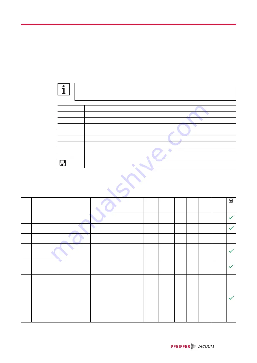
002 Stand-by

Stand-by

0 = off
1 = on

0

RW

0

1

0

006 Auto stdby

automatic 

standby

not supported

0

RW

0

1

0

009 ErrorAckn

Malfunction ac-

knowledgement

1 = Malfunction acknowl-

edgement

0

W

1

1

010 PumpgStatn

Pumping station

0 = off
1 = on and malfunction ac-

knowledgment

0

RW

0

1

0

011 Auto boost

automatic boost 

operation
(Not supported)

0 = off
1 = on

0

RW

0

1

0

019 Cfg DO2

Output DO2 

configuration

0 = Switch-point reached
1 = No error
2 = Error
5 = Set rotation speed 

reached
6 = Pump on
9 = Always "0"
10 = Always "1"
11 = Remote priority active

7

RW

0

21

5

Parameter set

35/68

Summary of Contents for SMARTVANE 55

Page 1: ...OPERATING INSTRUCTIONS EN Translation of the Original SMARTVANE 55 70 Rotary vane pump ...

Page 2: ...feiffer vacuum de Further operating instructions from Pfeiffer Vacuum can be found in the Download Center on our website Disclaimer of liability These operating instructions describe all models and variants of your product Note that your product may not be equipped with all features described in this document Pfeiffer Vacuum constantly adapts its products to the latest state of the art without pri...

Page 3: ... 18 3 1 2 Operating fluid 19 3 1 3 Cooling 19 3 2 Connections 19 3 3 Identifying the product 19 3 4 Product features 19 3 5 Scope of delivery 19 4 Transportation and Storage 21 4 1 Transporting vacuum pump 21 4 2 Storing vacuum pump 22 5 Installation 23 5 1 Setting up vacuum pump 23 5 2 Connecting the vacuum side 24 5 3 Connecting exhaust side 24 5 4 Filling up operating fluid 25 5 5 Connecting to...

Page 4: ...5 9 1 Maintenance instructions 45 9 2 Checklist for inspection and maintenance 46 9 3 Changing operating fluid 47 9 3 1 Draining operating fluid 48 9 3 2 Filling up operating fluid 49 9 3 3 Rinsing and cleaning rotary vane vacuum pump 49 9 4 Maintaining operating fluid separator 50 9 4 1 Dismantling exhaust filters 50 9 4 2 Mounting exhaust filters 51 10 Decommissioning 52 10 1 Shutting down for l...

Page 5: ...e inputs 37 Tbl 12 Configure parameters P 019 and P 024 41 Tbl 13 Configure parameter P 063 42 Tbl 14 Parameter P 060 42 Tbl 15 Behavior and meaning of the LEDS of the electronic drive unit 44 Tbl 16 Behavior and meaning of the LED standby 44 Tbl 17 Maintenance intervals 46 Tbl 18 Troubleshooting for rotary vane pumps 55 Tbl 19 Error messages of the electronic drive unit 56 Tbl 20 Warning messages...

Page 6: ... the electronic drive unit 29 Fig 9 Connection diagram of 15 pin remote connection 29 Fig 10 Connecting a control unit via the remote connection 31 Fig 11 Cross link via connection RS 485 using connection cables and accessories 32 Fig 12 Checking operating fluid level at sight glass 40 Fig 13 Filling up operating fluid 41 Fig 14 Draining operating fluid 48 Fig 15 Filling up operating fluid 49 Fig ...

Page 7: ...plicable for SmartVane line vacuum pumps SmartVane 55 SmartVane 70 1 2 Target group These operating instructions are aimed at all persons performing the following activities on the product Transportation Setup Installation Usage and operation Decommissioning Maintenance and cleaning Storage or disposal The work described in this document is only permitted to be performed by persons with the approp...

Page 8: ... 37 kg mass 1 75 L Oil quantity Year 2022 1 100 127 V 200 240 V 10 50 60 Hz 10A IP20 PK D80 001 Rating plate example Rating plate of the rotary vane vacuum pump Warning hot surface This sticker warns of injuries caused by high temperatures as a result of contact without protection during operation Electrical voltage warning The sticker warns of the risk of electric shock when working with the hous...

Page 9: ...peed value of a vacuum pump frequency in rpm or Hz FCC Federal Communications Commission USA N A not connected N N Mean sea level NRTL Nationally Recognized Test Laboratory P xxx Parameters are printed in bold as three digit numbers in square brackets Example P xxx Software version PC Personal computer PE Protective earth earthed conductor PFC Power factor correction circuitry in power supply pack...

Page 10: ...otes tips or examples indicate important information about the product or about this docu ment 2 2 Safety instructions All safety instructions in this document are based on the results of the risk assessment carried out in accordance with Machinery Directive 2006 42 EC Annex I DIN EN ISO 12100 Chapter 5 and DIN EN 1012 2 Where applicable all life cycle phases of the product were taken into account...

Page 11: ...uum pump not attached tipping over due to changes in the center of gravity or incorrect loading Serious injuries due to trapping or crushing of limbs e g feet are the re sult Do not use the vacuum pump as a climbing aid Do not exert any force on the product Ensure that the product has a safe centre of gravity when mounting components Wear protective equipment e g protective shoes WARNING Risk of f...

Page 12: ...f injury and fatality due to poisoning in processes with toxic process media Observe the pertinent regulations for handling toxic process media Safely purge toxic process media via an exhaust line Use appropriate filter equipment to separate toxic process media WARNING Risk of burns from ejected hot oil mist During operation hot pressurized oil mist escapes from the operating fluid separator Only ...

Page 13: ...of burns on hot surfaces Depending on the operating and ambient conditions the surface temperature of the vacuum pump can increase to above 70 C If access to the vacuum pump is unrestricted there is a danger of burns due to contact with hot surfaces Install suitable touch protection if the vacuum pump is accessible to untrained persons Allow the vacuum pump to cool down before carrying out any wor...

Page 14: ...ing Serious injuries due to trapping or crushing of limbs e g feet are the re sult Do not use the vacuum pump as a climbing aid Do not exert any force on the product Ensure that the product has a safe centre of gravity when mounting components Wear protective equipment e g protective shoes CAUTION Scalding from hot operating fluid Danger of burns when draining operating fluid if it comes into cont...

Page 15: ...he operator is required to check and re evalu ate the conformity of the overall system in the context of the relevant European Direc tives before commissioning that system General safety precautions when handling the product Observe all applicable safety and accident prevention regulations Check that all safety measures are observed at regular intervals Do not expose body parts to the vacuum Alway...

Page 16: ...icles dust or condensate Pumping explosive media Pumping of media with a propensity to sublimation Pumping of fluids Using the vacuum pump in potentially explosive atmospheres Using the vacuum pump outside the specified area of application Using the vacuum pump to generate pressure Using the vacuum pump with a vacuum flange that is open to the atmosphere Using in systems in which sporadic loads an...

Page 17: ...tion commissioning troubleshooting and maintenance of the product and who have the following qualifications Qualification in the electrical engineering field in accordance with nationally applicable regulations Knowledge of this documentation In addition these individuals must be familiar with applicable safety regulations and laws as well as the other standards guidelines and laws referred to in ...

Page 18: ...ction and compressed in the suction chamber by the rotation of the rotor until the exhaust valve opens against the atmospheric pressure and the gas leaves the suction chamber Scan the QR code or click here to see how single stage Pfeiffer Vacuum rotary vane pumps work 1 2 3 4 5 6 11 7 8 9 10 Fig 2 Structure of the rotary vane pump 1 Protective cap for DN 40 vacuum connection 7 Axial fan only for S...

Page 19: ...button Switches the vacuum pump and all components connected on or off depending on their configuration Corresponds with parameter P 010 Accessory connection 2 micro USB sockets C and D for connecting accessories Tbl 4 Interfaces of the electronic drive unit 3 3 Identifying the product To ensure clear identification of the product when communicating with Pfeiffer Vacuum always keep all of the info...

Page 20: ... Locking caps or blank flange plugs for vacuum and exhaust connection depending on the lubri cant version Operating instructions Product description 20 68 ...

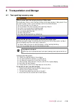
Page 21: ...m resulting in the vane breaking when the vacuum pump is switched on Always transport the vacuum pump horizontally or without operating fluid filling Fill in the operating fluid only at the final installation location Preparations for transport Pfeiffer Vacuum recommends keeping the transport packaging and original protective cov er Safe transport of the product Observe the weight specified on the...

Page 22: ...g fluid usability is limited max 2 years Prior to recommissioning following a shutdown of 2 years or more carry out the following work Change the operating fluid Replace all elastomer parts Observe the maintenance instructions consult Pfeiffer Vacuum if necessary Storage Pfeiffer Vacuum recommends storing the products in their original transport packaging Procedure 1 Seal the vacuum and exhaust fl...

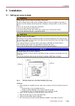
Page 23: ...e to untrained persons Allow the vacuum pump to cool down before carrying out any work Contact Pfeiffer Vacuum for suitable touch protection in system solutions NOTICE Property damage from external vibrations Vibrations impacts or strong oscillations originating externally can damage the bearings of the vac uum pump Do not store the vacuum pump in the vicinity of machines traffic routes or similar...

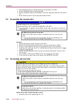
Page 24: ... er Vacuum component shop 5 Support or suspend the piping to the vacuum pump so that no piping system forces act on the vacuum pump 6 Use a separator or filter from the Pfeiffer Vacuum line of accessories if necessary 7 Connect the vacuum pump to the vacuum system using the vacuum connection 5 3 Connecting exhaust side CAUTION Danger of injury from bursting as a result of high pressure in the exha...

Page 25: ...rs Danger of poisoning if inhaled Observe the application instructions and precautions Do not allow tobacco products to come into contact with the operating fluid NOTICE Risk of damage due to the use of non approved operating fluid Product specific performance data are not achieved All liability and warranty claims against Pfeiffer Vacuum are also excluded Only use approved operating fluids Only u...

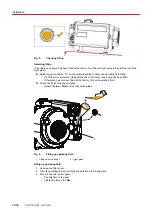
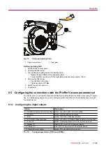
Page 26: ...rotary vane pump has been filled If the pump has not been filled at the factory fill it with operating fluid Check the fill level during operation Optimal fill level Middle of the inspection glass 1 2 Fig 6 Filling up operating fluid 1 Filling screw with seal 2 Sight glass Filling up operating fluid 1 Unscrew the filler screw 2 Fill with operating fluid according to the details on the rating plate...

Page 27: ...ife threatening voltages Unsafe or improper installation can lead to life threatening situations from electric shocks obtained from working with or on the unit Ensure safe integration into an emergency off safety circuit Do not carry out your own conversions or modifications on the unit WARNING Risk of fatal injury due to electric shock caused by water damage The device meets protection degree IP ...

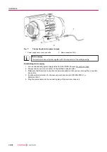
Page 28: ...responding power supply cable from the Pfeiffer Vacuum accessories range 2 Always ensure a secure connection to the earthed conductor PE 3 Make sure that the mains connection is easily accessible so that you can interrupt the connection at any time 4 Install overload protection for the vacuum pump according to DIN EN 60204 1 or DIN EN 61010 1 5 Plug the mains cable into the connecting plug of the ...

Page 29: ...ffers the possibility to operate the electron ic drive unit via remote control The following specifications are the factory settings for the electronic drive unit They can be configured with the Pfeiffer Vacuum parameter set Utilize the screened plug and cable 1 2 3 4 5 24 V DC RS 485 RS 485 n c 2 3 4 5 6 7 10 11 8 9 12 13 14 15 1 DI n c DI2 DI DI 24 V DC V DO1 DO2 RS 485 D RS 485 D FE 2 3 4 5 6 7...

Page 30: ...to switch various electronic drive unit functions Inputs are assigned with functions ex factory You can configure them via the RS 485 interface and the Pfeiffer Vacuum parameter set DI remote priority pin 2 V The remote connection has control priority over all other control sources open Remote priority inactive DI Pin 4 V On open Off DI pumping station pin 5 V Pumping station on and malfunction ac...

Page 31: ...connect the RS 485 interface to one external control unit only 6 3 Using RS 485 interface DANGER Danger to life from electric shock When establishing the voltages that exceed the specified safety extra low voltage according to IEC 60449 and VDE 0100 the insulating measures will be destroyed There is a danger to life from elec tric shock at the communication interfaces Connect only suitable devices...

Page 32: ...ty damage to third party electronic devices The accessory connections on the vacuum pump do not meet any USB standard The connection as signment does not comply with any standard Depending on their configuration the 24 V DC supply voltage may damage or destroy third party electronic devices e g tablet computer Do not connect any third party electronic devices to the accessory connections Only use ...

Page 33: ... 1 0 n2 n1 n0 0 6 N O _ D E F c2 c1 c0 cR _ R A N G E _ L O G I C NO_DEF Parameter number n2 n0 no longer exists _RANGE Data dn d0 outside the permissible range _LOGIC Logical access error 6 5 3 Telegram example 1 Data query Current rotation speed parameter P 309 device address slave 123 1 2 3 0 0 3 0 9 0 2 1 1 2 cR ASCII 49 50 51 48 48 51 48 57 48 50 61 63 49 49 50 13 Data response 633 Hz Current...

Page 34: ...haracter string with 6 charac ters ASCII codes between 32 and 127 06 TC_110 TM_700 6 boolean_new Logical value false true 01 0 is equivalent to false 1 is equivalent to true 7 u_short_int Positive whole number 03 000 to 999 10 u_expo_new Positive exponential number The last of both digits are the exponent with a deduction of 20 06 100023 is equivalent to 1 0 103 100000 is equivalent to 1 0 10 20 1...

Page 35: ...th the Pfeiffer Vacuum protocol Access type R read Read access W write Write access Unit Physical unit of the described variable min max Permissible limit values for the entry of a value default Factory default pre setting partially pump specific The parameter can be saved persistently in the electronic drive unit Tbl 8 Explanation and meaning of the parameters 7 2 Control commands Indicator Desig...

Page 36: ... setting mode On 7 RW 0 5 0 095 FactorySet Factory settings 1 Reset to factory configu ration 0 RW 0 1 0 Tbl 9 Control commands 7 3 Status requests Display Designations Func tions Data type Access type Unit min max de fault 300 RemotePrio Remote priority 0 no 1 yes 0 R 0 1 303 Error code Error code 4 R 304 OvTempElec Excess temperature drive electronics 0 no 1 yes 0 R 0 1 308 SetRotSpd Set rotatio...

Page 37: ...pe Unit min max de fault 707 SpdSVal Set value in rotation speed setting mode SmartVane 55 2 RW 60 100 100 Set value in rotation speed setting mode SmartVane 70 2 RW 45 100 100 717 StdbySVal Set value for rotation speed in stand by SmartVane 55 2 RW 60 100 80 Set value for rotation speed in stand by SmartVane 70 2 RW 45 100 60 721 SlgVlvTime Opening interval of gas ballast valve 2 RW min 0 60 5 73...

Page 38: ...r protective equipment e g protective shoes CAUTION Danger of injury if hair or loose clothing is pulled in There is a danger of injury from getting pulled in at rotating parts of the fan Do not wear loose fitting jewelry or hide it under clothing Wear close fitting clothing Use a hair net if necessary CAUTION Danger of injury from bursting as a result of high pressure in the exhaust line Faulty o...

Page 39: ...ct with hot surfaces Install suitable touch protection if the vacuum pump is accessible to untrained persons Allow the vacuum pump to cool down before carrying out any work Contact Pfeiffer Vacuum for suitable touch protection in system solutions NOTICE Malfunction of the oil return flow line from an intake pressure that is permanently too high In the long term operation with an intake pressure th...

Page 40: ...p operating fluid as required 8 4 Refilling operating fluid WARNING Danger of poisoning from toxic vapors Igniting and heating synthetic operating fluid generates toxic vapors Danger of poisoning if inhaled Observe the application instructions and precautions Do not allow tobacco products to come into contact with the operating fluid Required tools Allen key WAF 12 mm Required consumables Operatin...

Page 41: ...actory default basic functions and is ready for opera tion For individual requirements you can configure most connections for the electronic drive unit with the parameter set 8 5 1 Configuring the digital outputs Option Description 0 Rotation speed switchpoint reached active once the switch point is reached 1 No error active with trouble free operation 2 Error active if the error message is active...

Page 42: ...acuum pump without controller 1 Establish the current supply 2 Operate the vacuum pump with the on off and standby buttons Operating vacuum pump with external controller 1 Connect a remote control via the remote 15 pin D Sub socket 2 Control the vacuum pump by means of the PLC level Operating vacuum pump with peripheral device 1 Observe the operating instructions of the peripheral device 2 Connect...

Page 43: ... required value in 2 Set the parameter P 002 to 1 3 Check the set rotation speed parameter P 308 or P 397 8 7 3 Speed actuator operation Rotation speed setting mode reduces the speed and hence the throughput of the vacuum pump The pumping speed changes proportionally to the rotation speed Standby has priority over rotation speed setting mode The specification in rotation speed setting mode P 707 s...

Page 44: ... Off Standby OFF On constant Standby ON On inverse flashes twice Auto standby active Tbl 16 Behavior and meaning of the LED standby 8 9 Switching off vacuum pump Cycle operation Cycle operation with maximum 10 cycles per hour is possible Longer operating phases and short downtimes permit a functionally safe operating condi tion of the vacuum pump The Pumping station parameter P 010 comprises opera...

Page 45: ...still as a result of overheating the motor restarts automatically There is a risk of injury to fingers and hands if they enter the operating range of rotating parts Safely disconnect motor from the mains Secure the motor against reactivation Dismantle the vacuum pump for inspection away from the system if necessary NOTICE Danger of property damage from improper maintenance Unprofessional work on t...

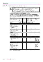
Page 46: ...lso applies if original spare parts are not used Action described in document Inspec tion OI Cleaning OI Mainte nance level 1 OI Maintenance level 3 MM Required material Interval Weekly every six months 2 years 4 years Inspection Visual and acoustic pump check Check the operating flu id filling level Check color contamina tion Check accessories in ac cordance with respective op erating instruction...

Page 47: ...ainst Pfeiffer Vacuum are also excluded Only use approved operating fluids Only use other application specific operating fluids after consultation with Pfeiffer Vacuum Maintenance frequency and service lives Maintenance frequency and service lives are process dependent Chemical and thermic loads or contamination reduce the recommended reference values Determine the specific service lives during th...

Page 48: ...hat it can be touched Operating fluid still warm 1 2 4 3 Fig 14 Draining operating fluid 1 Filling screw with seal 3 Collection receptacle 2 Drain screw with seal 4 Sight glass Draining operating fluid 1 Unscrew the filler screw 2 Place a collection receptacle below the drain hole 3 Unscrew the drain screw 4 Allow operating fluid to drain into collection receptacle 5 Screw the drain screw back in ...

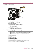
Page 49: ... 3 Rinsing and cleaning rotary vane vacuum pump Cleaning by changing the operating fluid Pfeiffer Vacuum recommends in cases of heavy contamination with process residues cleaning the inside of the vacuum pump with several operating fluid changes Prerequisites Fresh operating fluid filled Required aids Collection receptacle 2 l Change operating fluid for cleaning 1 Operate the vacuum pump until it ...

Page 50: ...ying out maintenance work Wear protective equipment WARNING Danger of poisoning from toxic vapors Igniting and heating synthetic operating fluid generates toxic vapors Danger of poisoning if inhaled Observe the application instructions and precautions Do not allow tobacco products to come into contact with the operating fluid Indications for saturation of the exhaust filter higher current consumpt...

Page 51: ...ns 9 4 2 Mounting exhaust filters Prerequisites Vacuum pump switched off Vacuum pump vented to atmospheric pressure Vacuum pump cooled Required consumables Maintenance kit Maintenance level 1 Required tools Allen key WAF 5 Calibrated torque wrench tightening factor 2 5 Procedure 1 Check whether the orifice has been installed at the new exhaust filter 2 Install the exhaust filter Pay attention to c...

Page 52: ...e covers 8 Store the vacuum pump in dry dust free rooms within the specified ambient conditions 9 Pack the vacuum pump together with a drying agent in a plastic bag and seal the vacuum pump airtight if it is to be stored in rooms with damp or aggressive atmospheres 10 For longer storage periods 2 years Pfeiffer Vacuum recommends changing the operating fluid again prior to recommissioning 10 2 Reco...

Page 53: ...d its components must be disposed of in accordance with the applica ble regulations relating to environmental protection and human health with a view to reducing natural resource wastage and preventing pollution 11 1 General disposal information Pfeiffer Vacuum products contain materials that you must recycle Dispose of our products according to the following Iron Aluminium Copper Synthetic Electr...

Page 54: ...f property damage from improper maintenance Unprofessional work on the vacuum pump will lead to damage for which Pfeiffer Vacuum accepts no liability We recommend taking advantage of our service training offering When ordering spare parts specify the information on the nameplate Vacuum pump and electronic drive unit malfunctions always result in a warning or error message In both cases you will re...

Page 55: ...eed of pump is too low Check the signals at the control input Exhaust pressure too high Check the exhaust line for clear passage Loss of operating fluid Operating fluid sep arator leaking Check for leaks Replace the seal as required Operational loss of operating fluid Check the exhaust filter and re place if necessary Unusual noises during operation Pumping system contaminated or damaged Clean and...

Page 56: ...an connecting cable for a correct fit and damage Improve the cooling Check the operating conditions Err045 Excess temperature motor Cooling inade quate Check to make sure the fan is work ing Check the fan connecting cable for correct fit and damage Improve the cooling Check the operating conditions Err093 Motor temperature evaluation faulty Contact Pfeiffer Vacuum Service Err094 Electronics temper...

Page 57: ... Wrn044 Electronics high tempera ture Cooling inade quate Check to make sure the fan is working Check the fan connecting cable for correct fit and damage Check the operating conditions Improve the cooling Wrn045 Motor high temperature Cooling inade quate Check to make sure the fan is working Check the fan connecting cable for correct fit and damage Check the operating conditions Improve the coolin...

Page 58: ...lity You can find more detailed information and addresses on our homepage in the Pfeiffer Vacuum Service section You can obtain advice on the optimal solution for you from your Pfeiffer Vacuum representa tive For fast and smooth service process handling we recommend the following 1 Download the up to date form templates Explanations of service requests Service requests Contamination declaration a ...

Page 59: ...oduct in suitable stable transport containers only e Maintain applicable transport conditions ERKLÄRUNG KONTAMINIERUNG 6 Attach the contamination declaration to the outside of the packag ing 7 Now send your product to your local Service Center 8 You will receive an acknowledgment quotation from Pfeiffer Vac uum Our sales and delivery conditions and repair and maintenance conditions for vacuum devi...

Page 60: ...e exhaust side 14 2 Ordering accessories Description Order number FAK 040 activated carbon filter PK Z30 008 SAS 40 dust separator PK Z60 510 Mains cable 230 V AC CEE 7 7 to C15 3 m PK 050 343 Mains cable 115 V AC NEMA 5 15 to C15 3 m PK 050 344 Y connector M12 for RS 485 P 4723 010 Adapter RS485 M12 PE 100 150 X OmniControl 001 Mobile control units PE D20 000 0 OmniControl 001 rack unit without i...

Page 61: ... 75 0 987 Pa m3 s 10 1 592 7 5 9 87 sccm 1 69 10 2 1 69 10 3 1 1 27 10 2 1 67 10 2 Torr l s 1 33 0 133 78 9 1 1 32 atm cm3 s 1 01 0 101 59 8 0 76 1 Tbl 24 Conversion table Units for gas throughput 15 2 Technical data Type designation SmartVane 55 SmartVane 55 SmartVane 70 SmartVane 70 Part number PK D80 000 PK D80 001 PK D81 000 PK D81 001 Connection flange in DN 40 ISO KF DN 40 ISO KF DN 40 ISO K...

Page 62: ...nternal Internal Protection degree IP20 IP20 IP20 IP20 Input voltage s 100 127 200 240 V AC 10 50 60 Hz 100 127 200 240 V AC 10 50 60 Hz 100 127 200 240 V AC 10 50 60 Hz 100 127 200 240 V AC 10 50 60 Hz Rotation speed 800 1 350 rpm 800 1 350 rpm 800 1 800 rpm 800 1 800 rpm Rated power at max rotation speed 0 75 kW 0 75 kW 1 kW 1 kW I O interfaces RS 485 RS 485 RS 485 RS 485 Operating fluid H1 F4 H...

Page 63: ...15 3 Dimensions 361 144 415 262 160 177 260 309 235 95 11 5 167 312 70 8 14 68 5 Fig 17 Dimensions of SmartVane 55 Technical data and dimensions 63 68 ...

Page 64: ...144 361 470 262 160 177 70 68 5 260 309 14 8 235 95 11 5 167 312 Fig 18 Dimensions of SmartVane 70 Dimensions in mm Technical data and dimensions 64 68 ...

Page 65: ...delegated directive 2015 863 EU Harmonized standards and applied national standards and specifications DIN EN ISO 12100 2011 EN 61000 3 2 2019 EN ISO 13857 2019 DIN EN 13849 1 2016 DIN EN 1012 2 2011 DIN EN 61326 1 2013 DIN EN ISO 2151 2009 DIN ISO 21360 1 2016 DIN EN 61010 1 2020 ISO 21360 2 2012 DIN EN IEC 61000 6 2 2019 DIN EN IEC 61000 6 4 2020 The authorized representative for the compilation...

Page 66: ... Substances in Electrical and Elec tronic Equipment Regulations 2012 Harmonized standards and applied national standards and specifications ISO 12100 2010 EN ISO 13849 1 2016 ISO 13857 2019 EN 61326 1 2013 EN 1012 1 2010 EN 1012 2 A1 1996 ISO 21360 1 2020 EN ISO 2151 2008 ISO 21360 1 2020 IEC 61010 1 2010 IEC 61000 3 2 2018 EN IEC 61000 6 2 2019 EN IEC 61000 6 4 2019 The manufacturer s authorized ...

Page 67: ...67 68 ...

Page 68: ... PD0114 ed A Date 2211 P N PD0114BEN ...

Reviews: