background image

2

www.pfisterer.com

Summary of Contents for MV-CONNEX 3

Page 1: ...allation Ins t r u c t i o n s r e a d y t o h a n d near the produc t MV CONNEX Size 3 3 S wire screen INSTALLATION INSTRUCTIONS Inner cone Take note of any additional instructions prior to installat...

Page 2: ...2 www pfisterer com...
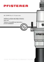
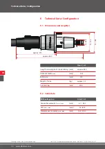
Page 3: ...www pfisterer com 3 Content...

Page 4: ...hgear is no lon ger required MV CONNEX The dry pluggable connection system for medium voltage networks Silicone a key material in medium voltage engineering Water dirt grease and oil resistant complet...

Page 5: ...ccessible in the immediate vicinity of the product e g control room switch room at all times 2 2 Contents of the installation instructions Any person who is tasked to perform work on or with the produ...

Page 6: ...e characteristics and further development 2 6 Guarantee The warranty provisions are contained in the purchase agreement and the manufacturer s general terms and conditions The manufacturer shall make...

Page 7: ...moving of the cable 3 2 Changes and modifications to the product To avoid hazards and to ensure optimum performance no changes nor ex tensions or alterations may be made to the product that are not ex...

Page 8: ...ages against the manufacturer or his authorised re presentative 3 6 Personnel requirements Skilled personnel means those who due to their technical training know ledge experience and understanding of...

Page 9: ...ways be worn Protective clothing tight fitting work clothing low tear resistance no long sleeves no rings or other jewelry etc Safety shoes for protection against heavy falling objects and slipping on...

Page 10: ...no agreement to the contrary has been made regarding the return of the packaging material the packaging material remains with the customer Disposal must be environmentally sound and in accordance wit...

Page 11: ...placed two years after production date 4 4 Storage Time 4 5 Disposal If no return or disposal agreement has been made disassembled compo nents should be dispossed of as below Scrap the metallic materi...

Page 12: ...llation Accessories 5 1 Tools required Special tools are required for assembly and disassembly Name Item No Description Hydraulic compression tool Compression head Size 3 Impact head Size 3 T handle s...

Page 13: ...mping tool Outside diameter of compression sleeve V Name Item No Description Assembly tool for CONNEX cable terminal heads in case Size 3 Size 2 3 Size 1 3 Consisting of hydraulic handheld crimping pl...

Page 14: ...ding heat shrink tubing Outer diameter max Bolt circle Weight Piece Contact ring With voltage tap Size 3 3 S Conductor diameter min max CSA min max Diameter over insulation min max VI mm approx 460 mm...

Page 15: ...ng impulse Partial discharge DC testing Rated short time current Rated impulse current VI In A 1250 1250 Um kV 42 52 50 Hz 5 min kV 95 117 1 2 50 s kV 200 250 2 x U0 pC 10 10 15 min 6 x U0 kV 125 156...

Page 16: ...ulating part Capacitive voltage tap optional Screws M8 x 45 Gasket Bell flange Capacitive voltage tap optional Heat shrink tubing Technical Data Configuration VI Drawings not to scale for information...

Page 17: ...flattening allowed the cable must be round a b Eccentricity Flattening Installation of the product where the above limits are not com plied with may cause damage If limits are exceeded the cable must...

Page 18: ...ductive the conductive layer must be removed up to 500 mm behind the jacket cut 1 e g by peeling grinding washing Installation Assembly VIII The installation is to be carried out in a clean and dry en...

Page 19: ...1 155 1 110 160 Installation Assembly VIII 1 110 160 Clean roughed area 3 1 4 1 Flame the roughened area Slide the smaller heat shrink tubing over the cable to line it and shrink it on in the roughene...

Page 20: ...her 45 mm behind the jacket cut 1 7 1 Only for cables with outer diameter 58 mm Apply woven insulating tape from the outer jacket for 40 mm to the jacket cut 1 with a 50 overlap 8 1 At the jacket cut...

Page 21: ...13 1 Tap down screen wires on the jacket cut 1 and either side of the sealing tape 14 1 Fold the screen wires in parallel without crossing over Important for water tightness Mark end of the cable 300...

Page 22: ...eelable semi conductive layer Peel semi conductive layer using the peeling tool to 40 mm in front of the jacket cut 1 Note instructions for the peeling tool 17 1 130 85 20 140 85 10 Only with strippab...

Page 23: ...ve wrapping 23 1 24 1 Apply an additional conductive layer of dry graphite that forms a good covering approx 40 mm on the semi conductive layer and insulation Take care to ensure insulation length of...

Page 24: ...er must be sealed Only with fine wire stranded conductor Stretch self amalgamating semi conductive tape lengthwise over approximately half the length and cut off the end Apply the 20 mm semi conductiv...

Page 25: ...aring the insulation diameter with application of the insulating part Check if the diameter of the insulation is within the working range of the insulating part see label packing list insulating part...

Page 26: ...wrapping over the conductive layer 2 1 Slide the heat shrink tubing and bell flange over the cable 3 1 Clean the insulation Recommended cleaning agents benzine acetone 4 1 Grease the insulation thinly...

Page 27: ...e the thrust piece onto the conductor with the rounded side to wards the insulating part 10 1 Slide the tension cone onto the conductor up to the thrust piece 11 1 The conductor must not protrude past...

Page 28: ...ter 5 1 page 12 Impact head Slide the retaining ring of the compression head back and fix the half shells behind the thrust piece 14 1 Do not damage the insulator VIII Installation Assembly Squeeze th...

Page 29: ...ntact ring onto the tension cone with the hydraulic com pression tool until it reaches pressure 17 1 Release the hydraulic compression tool 2 18 1 Slide the retaining ring of the press head back and o...

Page 30: ...s benzene acetone and grease thinly and evenly with PFISTERER MV spe cial grease Wear clean protective gloves e g latex or plastic 23 1 Clean the surface of the socket recommended cleaning agents ben...

Page 31: ...26 1 21 22 41 42 25 21 22 23 24 25 26 27 28 29 31 32 33 34 35 36 37 38 39 30 40 207 VIII Installation Assembly Using the ruler check the position of the control dimension 207 mm If not acheived press...

Page 32: ...dhesive tape 29 1 The test lead of the voltage tap may not cross over the screen wires and must run at a min distance of 10 mm parallel to the screen wires Apply a further layer of sealing tape direct...

Page 33: ...stem The earthing point is not suitable for earthing the cable screen Cut the screen wires not the test lead to the required length and connect it to the earthing of the system 1 1 The bell flange pro...

Page 34: ...cable connector Preparation of bushing socket The sealing set is only to be used in combination with the screws the Usit rings the washer and the Hylomar Completely fill the countersinks in the socke...

Page 35: ...ter the sealing tape with duct tape 1 1 Bundle the screen wires together 2 1 Apply the long slim heat shrink tubing over the screen wires 3 1 Apply the cable lug 4 1 Place two more layer of sealing ta...

Page 36: ...Assembly VIII Peel semiconductor layer using the peeling device to 60 mm in front of the outer jacket note instructions for the peeling device 4 1 Re apply the screen wires 5 1 Apply woven insulating...

Page 37: ...d with the SW6 T handle screwdriver 2 1 3 1 Remove heat shrink tubing The screen wires underneath the shrinkable tubing and the test lead of the voltage tap must not be damaged Pull the CONNEX termina...

Page 38: ...ing ring of the compression head to the back 7 1 Place the half shells of the compression head behind the removal tools and press together 8 1 Slide the retaining ring forward 9 1 Turn the knurled whe...

Page 39: ...Dismantling Removal IX Pull the contact ring off the tension cone with the hydraulic compres sion tool 11 1 Slide the retaining ring of the compression head back and open the half shells 12 1 Release...

Page 40: ...volta ge proof blind cap Position blind cap and tighten screws 1 1 The socket and insulating part of the separable connector must be cleaned and lubricated with special grease MV which can be ordered...

Page 41: ...g voltage Size 3 S U0 UN UM 26 45 52 kV Size 3 U0 UN UM 20 8 36 42 kV max test voltages Size 3 S VLF 3xU0 78 kV 60 min PD 2xU0 52 kV 10 pC Size 3 VLF 3xU0 63 kV 60 min PD 2xU0 42 kV 10 pC MV CONNEX te...

Page 42: ...andard instructions wire screen No 040 371 001 2014 05 08 i 01 10 4 Sheath testing Carry out the sheath testing at max 5 kV DC voltage Connect the DC voltage 1 1 G X Loosen earth screen and test lead...

Page 43: ...nd layer of sealing tape directly on the first thus fixing the wires 2 1 Shrink heat shrink tubing over bell flange and cable 3 1 Option 2 Fix the screen wires after the sealing tape with duct tape 1...

Page 44: ...structions wire screen No 040 371 001 2014 05 08 i 01 12 Unplugging Plugging in 12 1 Unplugging Loosen cable screen test lead if present and remove the earthing of the bell flange 1 1 Loosen the mount...

Page 45: ...not voltage proof or blind cap permanent raise 3 1 Clean the inside of the socket recommended cleaning agents benze ne acetone and grease thinly and evenly with PFISTERER MV special grease Wear clean...

Page 46: ...ective gloves e g latex or plastic Do not apply grease to the contact area 2 1 Introduce the CONNEX separable connector into socket and screw in the screws 3 1 The bell flange must be held with pressu...

Page 47: ...n only Size 3 3 S Standard instructions wire screen No 040 371 001 2014 05 08 i 01 Tighten the screws all round with the SW6 T handle screwdriver tor que 15 Nm 4 1 A settling time of 1 hour is needed...

Page 48: ...ERER Sp z o o ul Pogodna 10 05 850 Piotrkowek Maly Poland Phone 48 22 72241 68 Fax 48 22 72127 81 E Mail info pfisterer pl PFISTERER Russia Verkaufsb ro Krasnopresnenskaya nab 12 Entrance No 6 offic n...

Reviews: