06HULHV__5HY$__HPDLOSVG#SÁRZFRP
6HFWLRQ_
Section 7 |
Mechanical Overview
www.pflow.com
P 414 352 9000
F 414 352 9002
6720 N. Teutonia Ave.
Milwaukee, WI 53209
Each M series (mechanical) Vertical Reciprocating Conveyor (VRC) consist of
two (2) columns, a drivebase assembly with a gearmotor reducer, drive shaft
with two (2) lift sprocket assemblies, a moving carriage deck, and if furnished,
interlocked safety gates or doors. In addition, a main control panel and typically
at least one push-button station per level are furnished. For more information on
the electrical components, see Section 8 in this manual.
The M series consists of two (2) vertical upright columns. These are anchored
to the floor at the lower floor level, positioned by the drivebase at the top, and
braced to the building structure at the upper and intermediate levels.
Each column has a guide angle welded to one flange of the column to form a
track. A chain tube guard is welded to the face of the other flange.
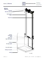
There are two (2) configuration types available for this model. “Straddle” has a
column located on each side of the carriage. The guide angles face each other
allowing the carriage to ride between them. See Figure 7-1. “Cantilever” has both
columns located at the back of the carriage. See Figure 7-2. There is no difference
in the operation or maintenance between these models.
Lift Columns
Mechanical
Overview
Straddle /
Cantilever
&RQÀJXUDWLRQ
9
1. Drivebase Assembly
2. Second Level
Push-button Station
3. Overtravel Limit Switch
4. Second Level Limit Switch
5. Disconnect Switch
6. First Level
Push-button Station
7. Main Control Panel
8. First Level Limit Switch
9. Columns
10. Carriage
18613-0100.SMG
PFL-200114
1
2
3
4
5
6
7
8
10
Straddle Orientation Figure 7-1
Carriage
Drivebase and
Sprocket Assembly
Columns
12150-1000-S.SMG
PFL-1216-1
Overtravel Limit Switch
2nd Floor Limit Switch
1st Floor Limit Switch
Cantilever Orientation Figure 7-2

