background image


PFT ROTOQUIRL II/ PFT ROTOMIXSafety - Overview - Operation - Spare parts lists 

Fitting the pump to Rotoquirl


2016-08-26


33 


21.1 Install the machine on a stable surface 


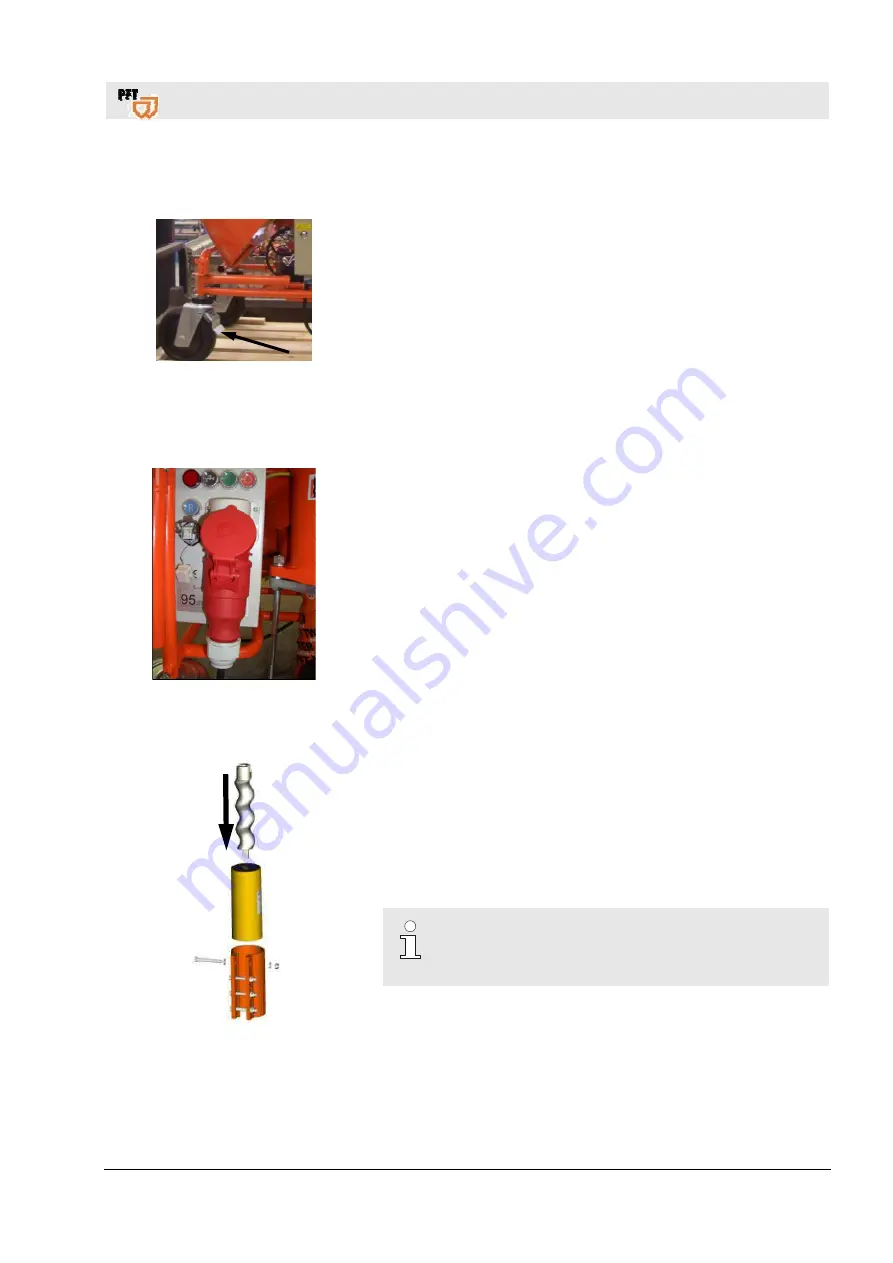
Fig. 29:Lockable castor 

1

.

  Lock the lockable castor prior to operating the machine. 

2

.

  Place the machine on a stable, even surface and secure 

against unwanted movements: 

  Neither tilt nor roll off the machine. 

  Put up the machine in such a way that it cannot be hit by 

falling objects.  

  The operating elements have to be freely accessible. 


21.2 Attaching the pump 


Fig. 30:Disconnect the power connection 

Disconnect the power connection at the control cabinet of the 
cleaning machine. 

Interrupt the control circuit by removing the dummy plug from the 
control cabinet. 

21.3 Fitting the pump system 


Fig. 31:Assembling the pump


Turn the screw conveyor with tang in the spiral casing (pay 
attention to the arrow on the spiral casing). 

Fit clamping bracket. 


NOTE! 

Never let the pump run dry as this reduces the service 
life of the pump. 


Summary of Contents for 00 03 98 68

Page 1: ...1 84 00 ROTOQUIRL JUMBO Article number 00 03 98 68 ROTOMIX D pump Article number 20 11 80 00 ROTOMIX R pump Article number 20 11 80 50 ROTOMIX DISC Article number 00 20 93 75 ROTOMIX RITMO B PUMP Article number 00 14 73 53 Article number 00 25 11 39 Article number of the operating manual 00 47 64 64 Read the operating manual prior to starting any work ...

Page 2: ...016 08 26 Knauf PFT GmbH Co KG P O Box 60 97343 Iphofen Einersheimer Straße 53 97346 Iphofen Germany Phone 49 9323 31 760 Fax 49 9323 31 770 Technical hotline 49 9323 31 1818 info pft iphofen de www pft eu ...

Page 3: ...IX D pump 18 8 Dimension sheet ROTOQUIRL II 20118400 19 9 Dimension sheet ROTOMIX 20118050 20118000 00209375 19 10Dimension sheet Rotoquirl JUMBO 00039868 20 11Dimension sheet Rotomix Ritmo B pump 00147353 20 12Overview ROTOQUIRL Jumbo 00 03 98 68 21 13Overview ROTOQUIRL II 20 11 84 0022 14Overview ROTOMIX No 20 11 80 00 23 15Overview ROTOMIX B pump 00 14 73 53 24 16Advantages of PFT ROTOQUIRL ROT...

Page 4: ...aintenance 40 29 1 Maintenance work on the machine 40 29 2 Measures after completed maintenance 41 30Environmental protection 42 31Disassembly 42 31 1 Safety 42 31 2 Disassembly 43 31 3 Disposal 43 32Spare parts drawing spare parts list 44 32 1 ROTOQUIRL II 20 11 84 00 44 32 2 ROTOQUIRL II 20 11 84 00 45 32 3 ROTOMIX R pump 20 11 80 50 46 32 4 ROTOMIX R pump 20 11 80 50 47 32 5 ROTOMIX D pump 20 1...

Page 5: ...es of facts not necessarily to scale and may slightly differ from the actual model of the device 1 2 Keeping the manual for future reference The operating manual has to be available during the whole service life of the product 1 3 Information regarding the safety instructions These safety instructions give important information on handling the device A prerequisite for safe working is the observan...

Page 6: ...juries or material damage DANGER F indicates an immediate dangerous situation which leads to severe injuries or death if not averted WARNING F indicates a possibly dangerous situation which may lead to severe injuries or death if not averted ATTENTION F indicates a possibly dangerous situation which may lead to minor injuries if not averted ATTENTION F indicates a possibly dangerous situation whic...

Page 7: ...en compiled considering the applicable standards and regulations the state of the art as well as our long time expertise and experience The manufacturer is not responsible for any damage in the following cases Non compliance with the manual Improper use Appointing untrained staff Unauthorized modifying Technical modifications Use of non standard spare parts The actual scope of delivery may vary fr...

Page 8: ...ted without a written declaration from the manufacturer Violations may lead to damage compensation Other claims are reserved 4 Spare parts WARNING Danger of injury due to wrong spare parts Wrong or defective spare parts can cause damage malfunctioning or total breakdown as well as hamper the safety Therefore Use only original spare parts provided by the manufacturer Buy spare parts from an authori...

Page 9: ...ment which are present due to special working conditions at the operational site of the tool He must implement these in form of operating instructions for operating the tool During the entire time of use the operator must check if the operating instructions created by him comply with the current regulations and adjust them if required The operator must regulate and fix responsibilities for install...

Page 10: ...illed personnel carry out the work allotted to them due to their technical qualification skills and experience as well as knowledge of the relevant regulations and are aware of the possible risks on their own Electricians carry out the work on electrical systems due to their technical qualification skills and experience as well as knowledge of the relevant standards and regulations and are aware o...

Page 11: ...he tool is conceptualised and designed exclusively for the purpose of use specified here The PFT ROTOMIX ROTOQUIRL helps to burst the bigger air bubbles in the mortar and thus in stabilisation WARNING Danger due to improper use Any case of use beyond the specified purpose of use and or any other sort of use of the tool can lead to dangerous situations Therefore Use the tool only for the purpose sp...

Page 12: ...arrow sleeves and without parts sticking out It mainly helps to protect from getting stuck in moving machine parts Do not wear any rings chains and other jewellery Safety shoes for protecting from heavy parts that may fall and from slipping on slippery floors Protective goggles to protect the eyes from parts that may fly around and liquid splashes Simple breathing mask for protection from harmful ...

Page 13: ... in the other chapters of the manual in order to reduce the health risks and to avoid dangerous situations Electric current DANGER Danger of death from electric current There is danger of immediate death if live parts are touched Damage to insulation or individual parts can be fatal Therefore Switch off the power supply immediately if the insulation is damaged and arrange for repairs Work on the e...

Page 14: ...s wear ear protection while working Check only in the danger zone as long as necessary Hazardous dusts WARNING Health hazard caused by dust In the long term inhaled dust can lead to lung damage or have other adverse health effects Therefore Wear a simple breathing mask for all work in the danger zone Moving components WARNING Risk of injury due to moving components Rotating and or linear moving co...

Page 15: ...safety in operation Even if work processes become a little more complicated due to safety equipment they must never be decommissioned Safety is guaranteed only with intact safety equipment Therefore Before starting work check if the safety equipment is functioning properly and has been correctly installed Use safety equipment at all times Do not obstruct access to safety systems such as emergency ...

Page 16: ...octor and or the fire brigade Make access routes free for emergency vehicles 6 9 Labelling The following symbols and warning signs can be seen in the work area They refer to the environment in which they are installed WARNING Danger of injury due to illegible symbols With time the adhesive and the signs can become dirty and fade out in some other way Therefore Keep all safety warning and operating...

Page 17: ...t 9 2 lt Weight ROTOQUIRL 28 2 kg Coupling 35 7 2 Cover ROTOQUIRL II Fig 2 Cover Rotoquirl 20 11 84 07 Cover ROTOQUIRL R pumps 7 3 Technical data ROTOQUIRL II Fig 3 Rotoquirl Article number PFT ROTOQUIRL D pump 20 11 84 00 Detail Value Unit Content 4 2 lt Weight ROTOQUIRL 23 kg Coupling 35 7 4 Technical data ROTOMIX Fig 4 Rotomix D PUMP Article number PFT ROTOMIX D pump 20 11 80 00 Detail Value Un...

Page 18: ... Detail Value Unit Content 0 25 lt Weight ROTOMIX 6 0 kg Coupling 25 mm 7 6 Technical data ROTOMIX R pump Fig 6 Rotomix R pump Article number PFT ROTOMIX R pump 20 11 80 50 Detail Value Unit Content 1 2 lt Weight ROTOMIX 10 10 kg Coupling 35 mm 7 7 Technical data ROTOMIX D pump Fig 7 Rotomix DISC Article number PFT ROTOMIX disc D pump 00 20 93 75 Detail Value Unit Content 1 2 lt Weight ROTOMIX 11 ...

Page 19: ...rview Operation Spare parts lists Dimension sheet ROTOQUIRL II 20118400 2016 08 26 19 8 Dimension sheet ROTOQUIRL II 20118400 Fig 8 Dimension sheet ROTOQUIRL 9 Dimension sheet ROTOMIX 20118050 20118000 00209375 Fig 9 Dimension sheet ROTOMIX ...

Page 20: ...mension sheet Rotoquirl JUMBO 00039868 20 2016 08 26 10 Dimension sheet Rotoquirl JUMBO 00039868 Fig 10 Dimension sheet ROTOMIX Fig 11 Dimension sheet ROTOMIX 1 11 Dimension sheet Rotomix Ritmo B pump 00147353 Fig 12 Dimension sheet ROTOMIX 2 Fig 13 Dimension sheet ROTOMIX 3 ...

Page 21: ...ew ROTOQUIRL Jumbo 00 03 98 68 2016 08 26 21 12 Overview ROTOQUIRL Jumbo 00 03 98 68 Fig 14 Overview Rotoquirl 00 03 98 68 1 2 3 6 5 4 1 Lock ring for ROTOQUIRL 2 Tie rod M16 x 330 mm 3 Cover ROTOQUIRL 4 Housing ROTOQUIRL II 5 Coupling reduction 35V 25V part LW 24 6 Double mixer ...

Page 22: ...TOQUIRL II 20 11 84 00 22 2016 08 26 13 Overview ROTOQUIRL II 20 11 84 00 Fig 15 Overview Rotoquirl 20 11 84 00 1 2 3 6 5 4 1 Lock ring for ROTOQUIRL 2 Tie rod M16 x 330 mm 3 Cover ROTOQUIRL 4 Housing ROTOQUIRL II 5 Coupling reduction 35V 25V part LW 24 6 Mixing impeller ROTOQUIRL II ...

Page 23: ...w ROTOMIX No 20 11 80 00 2016 08 26 23 14 Overview ROTOMIX No 20 11 80 00 Fig 16 Overview Rotomix 20 11 80 00 1 2 3 6 4 5 1 Tie rod M16 x 390 mm 2 Mixing impeller ROTOMIX 3 Cover ROTOMIX 4 Housing ROTOMIX 5 Coupling 35V part coupling reduction 35V 25V part LW24 6 Coupling 35M part ...

Page 24: ...mp 00 14 73 53 24 2016 08 26 15 Overview ROTOMIX B pump 00 14 73 53 Fig 17 Overview Rotomix B PUMP 00 14 73 53 1 2 3 4 5 6 7 1 Tie rod M12 x 320 mm 2 Rotor ROTOMIX B PUMP 3 Suction flange ROTOMIX B PUMP 4 Stator ROTOMIX B PUMP 5 Cover ROTOMIX B PUMP 6 Housing ROTOMIX B PUMP 7 Coupling 25V part ...

Page 25: ...ODE OF OPERATION The bigger air bubbles in the mortar are burst in the remixer and thus stabilised Bursting of the air bubbles at the time of discharge from the mortar nozzle can thus no longer be seen This makes the mortar smoother and more efficient As a result of an intensive re mixing the mortar becomes completely doughy and has no knots such that easy quick and consistent processing is ensure...

Page 26: ...ROTOMIX ROTOQUIRL II and ROTOMIX G 4 up to machine number 93052432072 with a welded suction flange Fig 18 Rotoquirl with welded suction flange Fig 19 Rotomix with welded suction flange ROTOQUIRL II and ROTOMIX G 4 after machine number 93052432073 with a changeable suction flange Fig 20 Rotoquirl with changeable suction flange Fig 21 Rotomix with changeable suction flange ...

Page 27: ...ble transport damage proceed as follows Do not accept the delivery or under reserve only Note the extent of damage on the transport documentation or on the delivery note of the carrier Initiate complaint process NOTE Report any defect as soon as it is detected Claims for damages can be asserted only within the valid warranty period 18 3 Packaging Handling packaging materials If no agreement for th...

Page 28: ... for all operative work Protective clothing Protective goggles Protective gloves Safety shoes Hearing protection NOTE Further protective equipment that is to be worn for particular jobs will be pointed out separately in the warning instructions of this chapter Basic information WARNING Danger of injury due to incorrect operation Improper operation may lead to serious damage to persons or property ...

Page 29: ...ut the following steps for preparing the machine Tool required 2 x SW24 2 x SW19 1 x SW18 1 x SW13 1 x rubber mallet 20 2 Pressure in the mixing chamber Fig 23 Mortar pressure gauge DANGER Operating pressure too high The operating pressure in the remixer may not exceed 25 bar A PFT mortar pressure gauge is absolutely necessary Article number 00 10 22 28 Mortar pressure gauge 35M V PART galvanised ...

Page 30: ...ng 2 on the housing 5 support for the pump above in Fig 16 Screw the nuts 3 to the tie rod 4 Screw the tie rod 4 in the housing and secure with nuts 6 Screw the coupling 35 M part 7 to the housing Attach the coupling reduction 8 to the coupling 7 Attach the pump system tang of the rotor must be in the support of the mixing impeller Fig 25 Fig 25 Top support Fig 26 Rotor tang in the Rotomix mixing ...

Page 31: ... Place the cover 3 with the O ring 4 on the housing 2 support for the pump Place the lock ring 5 between the cover 3 and housing 2 Fit the lock ring 5 with a screw 6 to the cover 3 Brace the lock ring 5 by tightening the collar nut 7 Screw on the nut M 16 8 to the tie rod 9 approximately up to the centre of the thread Screw the tie rod 9 in the housing 2 and secure it 8 Screw the coupling 35 M par...

Page 32: ... Carry out all operating steps according to the instructions in this user manual Prior to starting your work ensure that all covers and protection devices are installed and work as intended Never deactivate protection devices during operation Ensure order and cleanliness in the work area Loose components and tools on top of one another or lying about pose potential accident risks Increased noise l...

Page 33: ... such a way that it cannot be hit by falling objects The operating elements have to be freely accessible 21 2 Attaching the pump Fig 30 Disconnect the power connection Disconnect the power connection at the control cabinet of the cleaning machine Interrupt the control circuit by removing the dummy plug from the control cabinet 21 3 Fitting the pump system Fig 31 Assembling the pump Turn the screw ...

Page 34: ...hine without fail 21 5 Remove the agitator DANGER Risk of contusion at the motor tilt flange There is a risk of contusion when closing the motor tilt flange Do not reach into the clamping area of the motor tilt flange Fig 32 Risk of contusion at the motor tilt flange Open the quick closure at the motor tilt flange and tilt the motor Fig 33 Open motor tilt flange Remove the agitator Fig 34 Remove t...

Page 35: ...35 Remove the suction flange Fit the suction flange to the remixer Fig 36 Fitting the suction flange Attach the remixer with a fitted suction flange to the pump tube Tighten the collar nuts Attach the mortar pressure gauge Fig 37 Attach remixer and mortar pressure gauge Install the agitator and close the motor tilt flange Close the quick closure The cleaning machine is again fit for use Fig 38 Ins...

Page 36: ...erial is determined depending on the respective mortar If a remixer is attached the break times must be reduced by approximately 1 3 to avoid settling of the mixing impeller In case of a longer standstill the remixer must be dismounted and cleaned Longer breaks should be avoided as otherwise there is a risk that the mortar will solidify in the pump remixer and the hoses NOTE The guidelines of the ...

Page 37: ...d material Other persons have to clear the area Turn the main switch to position 0 Fig 40 Pressure gauge DANGER Overpressure on the machine When opening machine parts they can open in an uncontrolled manner and injure the operator Open the mortar hoses only when the pressure has dropped to 0 bar Switch off the main switch immediately Secure the main switch on the cleaning machine against restartin...

Page 38: ...discharged 25 Work for rectifying faults 25 1 Reaction in the event of faults Reaction in the event of faults Fig 41 Switching off emergency stop The following strictly applies 1 In the event of faults presenting immediate danger to persons or property activate the emergency stop function immediately 2 Determine cause for fault 3 If the rectification of faults requires works in the danger zone swi...

Page 39: ...ction 26 Switching off 26 1 In case of clogging in hoses DANGER Danger from discharged material Persons commissioned with the cleaning of clogged hoses have to wear personal protective equipment protective goggles gloves for safety reasons and to position themselves in such a way that they cannot be hit by discharged material Other persons have to clear the area 27 Cleaning 27 1 Cleaning the remix...

Page 40: ...onger power cut the material hoses have to be cleaned immediately Before opening the couplings ensure that there is no more pressure on the hoses observe display at mortar pressure gauge 29 Maintenance 29 1 Maintenance work on the machine Basic information WARNING Risk of injury due to improperly carried out maintenance work Improper maintenance can lead to severe injuries or considerable property...

Page 41: ...at the energy supply is switched on without authorisation This poses a danger to life for the persons in the danger area Therefore Switch off all energy supplies before starting any works and secure against restarting 29 2 Measures after completed maintenance After finishing the maintenance works and prior to switching on the machine the following steps have to be carried out 1 Check all previousl...

Page 42: ...y by specially trained technical personnel Work on the electrical system must be carried out by qualified electricians only Basic information WARNING Risk of injury in case of improper disassembly Stored residual energies sharp components points or edges at and inside the device or on the required tools might cause injuries Therefore Prior to starting the works ensure that there is sufficient spac...

Page 43: ...cure against restarting Physically separate the complete energy supply from the device discharge stored residual power Remove operating supplies as well as remaining processing materials and dispose of them in an environment friendly way 31 3 Disposal If no agreement for the recovery or the disposal was made recycle the disassembled components Scrap metals Recycle plastic elements Dispose of remai...

Page 44: ...II PFT ROTOMIXSafety Overview Operation Spare parts lists Spare parts drawing spare parts list 44 2016 08 26 32 Spare parts drawing spare parts list 32 1 ROTOQUIRL II 20 11 84 00 1 2 3 3 4 5 6 7 15 8 14 13 12 11 10 9 ...

Page 45: ...RL R pumps not in the scope of delivery 3 1 20 11 84 03 Cover ROTOQUIRL D pumps RAL 2004 4 1 20 11 84 05 Lock ring for ROTOQUIRL 5 1 20 20 99 40 Hex screw M 10 x 50 galvanised 6 1 20 11 84 02 Mixing impeller ROTOQUIRL II 7 1 20 11 84 09 O ring 312 x 5 8 1 20 11 84 08 Housing ROTOQUIRL II 9 1 20 20 03 30 Coupling reduction 35V 25V part LW 24 10 1 20 20 07 12 Gasket 35M part VPE 10 11 1 20 20 07 90 ...

Page 46: ...PFT ROTOQUIRL II PFT ROTOMIXSafety Overview Operation Spare parts lists Spare parts drawing spare parts list 46 2016 08 26 32 3 ROTOMIX R pump 20 11 80 50 1 2 3 4 5 6 7 8 9 ...

Page 47: ... coupling and reduction 1 1 20 11 81 43 Cover ROTOMIX R pumps for O ring 2 1 20 11 81 42 O ring 138 x 6 3 1 20 11 81 93 Tie rod M16 x 390 mm ROTOMIX 1 set 2 pieces 4 1 20 11 81 92 Mixing impeller ROTOMIX 5 1 20 11 81 91 ROTOMIX housing with welded long nut 6 4 20 20 99 20 Hex nut M16 galvanised 7 1 20 20 07 90 Coupling 35M part 1 1 4 IG with gasket 8 1 20 20 07 12 Gasket 35M part VPE 10 9 1 20 20 ...

Page 48: ...PFT ROTOQUIRL II PFT ROTOMIXSafety Overview Operation Spare parts lists Spare parts drawing spare parts list 48 2016 08 26 32 5 ROTOMIX D pump 20 11 80 00 1 2 3 4 5 6 7 8 9 ...

Page 49: ... coupling and reduction 1 1 20 11 81 33 Cover ROTOMIX D pumps for O ring 2 1 20 11 81 42 O ring 138 x 6 3 1 20 11 81 93 Tie rod M16 x 390 mm ROTOMIX 1 set 2 pieces 4 1 20 11 81 92 Mixing impeller ROTOMIX 5 1 20 11 81 91 ROTOMIX housing with welded long nut 6 4 20 20 99 20 Hex nut M16 galvanised 7 1 20 20 07 90 Coupling 35M part 1 1 4 IG with gasket 8 1 20 20 07 12 Gasket 35M part VPE 10 9 1 20 20 ...

Page 50: ...PFT ROTOQUIRL II PFT ROTOMIXSafety Overview Operation Spare parts lists Spare parts drawing spare parts list 50 2016 08 26 32 7 ROTOMIX disc 00 20 93 75 1 2 3 4 5 6 7 8 9 10 11 ...

Page 51: ...ng 2 1 20 11 81 42 O ring 138 x 6 DIN 3771 NBR 70 3 1 20 11 81 93 Tie rod M16 x 390 mm ROTOMIX 1 set 2 pieces 4 1 00 20 93 83 Mixing impeller ROTOMIX disc RAL2004 5 2 00 03 57 54 Countersunk screw M10x 25 galvanised 6 1 00 20 93 55 Shearing disc ROTOMIX spattling compound RAL2004 7 1 00 20 94 13 Housing ROTOMIX disc RAL2004 8 4 20 20 99 20 Hex nut M16 galvanised 9 1 20 20 07 90 Coupling 35M part 1...

Page 52: ...PFT ROTOQUIRL II PFT ROTOMIXSafety Overview Operation Spare parts lists Spare parts drawing spare parts list 52 2016 08 26 32 9 ROTOQUIRL JUMBO 00 03 98 68 1 2 3 4 5 17 16 15 6 14 7 8 9 13 10 12 11 ...

Page 53: ...k ring for ROTOQUIRL 6 1 00 03 98 69 Jumbo double mixer RAL2004 for ROTOQUIRL Jumbo 7 1 20 11 84 09 O ring 312 x 5 8 1 00 04 85 67 Plastic spacer disc D70xd13x5 9 1 00 03 98 70 Housing ROTOQUIRL JUMBO double rollers RAL2004 10 1 00 03 47 12 Hex shoulder screw M12 x 28 twisted off 11 1 20 20 03 30 Coupling reduction 35V 25V part LW 24 12 1 20 20 07 12 Gasket 35M part 13 1 20 20 07 90 Coupling 35M p...

Page 54: ...PFT ROTOQUIRL II PFT ROTOMIXSafety Overview Operation Spare parts lists Spare parts drawing spare parts list 54 2016 08 26 32 11 ROTOMIX B pump 00147353 00251139 1 2 13 3 4 12 11 5 6 10 9 8 7 ...

Page 55: ...4 1 5 L W 7 tang 4 1 00 04 85 66 Stator B4 1 5L wf 5 1 00 14 73 49 Cover ROTOMIX RITMO RAL2004 6 1 00 14 73 93 Mixing impeller Rotomix RITMO RAL2004 7 6 20 20 69 00 Hex nut M12 galvanised 8 1 20 19 93 00 Coupling 25V part 1 IG LW 24 9 1 00 14 72 98 Housing ROTOMIX RITMO RAL2004 10 1 00 15 21 91 O ring 74 x 6 DIN 3771 NBR 70 11 2 20 20 99 90 Threaded rod M12 x 320 galvanised 12 2 00 25 12 71 Thread...

Page 56: ...g 17 Overview Rotomix B PUMP 00 14 73 53 24 Fig 18 Rotoquirl with welded suction flange 26 Fig 19 Rotomix with welded suction flange 26 Fig 20 Rotoquirl with changeable suction flange 26 Fig 21 Rotomix with changeable suction flange 26 Fig 22 Tool 29 Fig 23 Mortar pressure gauge 29 Fig 24 Rotomix assembly 30 Fig 25 Top support 30 Fig 26 Rotor tang in the Rotomix mixing impeller 30 Fig 27 Rotoquirl...

Page 57: ...FT ROTOMIXSafety Overview Operation Spare parts lists List of figures 2016 08 26 57 Fig 38 Installing the agitator 35 Fig 39 Switching off emergency stop 37 Fig 40 Pressure gauge 37 Fig 41 Switching off emergency stop 38 ...

Page 58: ...tection 12 Helmet 12 In case of clogging in hoses 39 Index 58 Information regarding the operating manual 5 Information regarding the safety instructions 5 Install the machine on a stable surface 33 Intended purpose 11 Interruption of work or end of work 36 Keep the manual for future reference 5 Liability 7 List of figures 56 Maintenance 40 41 Maintenance work on the machine 40 Measures in case of ...

Page 59: ...hoes 12 Signs 16 Skilled personnel 10 Spare parts 8 Spare parts drawing spare parts list 44 Spare parts list ROTOMIX disc 00 20 93 75 51 Spare parts list ROTOMIX R pump 20 11 80 5047 Spare parts list ROTOQUIRL II 20 11 84 00 45 Spare parts list ROTOQUIRL JUMBO 00 03 98 68 53 Special risks 13 Sticker 16 Storage 27 Switching off 39 Symbols in the danger zone 16 in the manual 6 Technical data 17 Tech...

Page 60: ...n Spare parts lists 60 2016 08 26 The FLOW OF PRODUCTIVITY Knauf PFT GmbH Co KG P O Box 60 97343 Iphofen Einersheimer Straße 53 97346 Iphofen Germany Phone 49 9323 31 760 Fax 49 9323 31 770 Technical hotline 49 9323 31 1818 info pft iphofen de www pft eu ...

Reviews: