background image


Mixing pump RITMO L / RITMO M Overview - Operation 


Intended use control panel 


20 


2016-02-17


13 Intended use control panel 

13.1 Intended purpose control panel 

The  tool  is  conceptualised  and  designed  exclusively  for  the 
purpose of use specified here. 


Scope of application: 

Primary  use  for  water  and  neutral,  non-adhesive 
liquids.  Also  suitable  for  air  and  neutral  non-
flammable gases. 

Maximum  operating  pressure  (inlet  pressure)  16 
bar. 

Outlet  pressure  infinitely  adjustable  from  1.5  to  6 
bar. 

Smallest possible inlet pressure 2.5 bar. 

Minimum  pressure  drop  (inlet  pressure/outlet 
pressure) 1 bar. 

Maximum media and ambient temperature 75°C. 

Assembly position as desired, preferable vertical. 


13.2 Intended purpose solenoid valve 


Scope of application: 

Solenoid  valves  for  liquid  and  gaseous  media, 
aggressive  or  neutral,  can  be  used  different 
temperature and pressure ranges 

Type 6213 is a 2/2 way solenoid valve with straight 
passage,  normally  closed,  with  a  permanently 
coupled  membrane  system.  It  operates  from  0  bar 
and can be used universally for liquids. A minimum 
pressure  differential  of  0.5  bar  is  required  for  the 
valve to fully open. 


13.3 Intended purpose flow meter 


Scope of application: 

The  flow  meter  is  used  for  the  volume 
measurement  of  transparent  liquid  and  gaseous 
flows  in  closed  pipelines.  Optionally  the  devices 
can be used for flow monitoring. 


Summary of Contents for 00 06 49 61

Page 1: ...eration RITMO L RITMO M Article number of the operating manual 00 14 14 08 Article number of the parts list machine RITMO L 00 22 22 56 00 24 64 44 00 23 20 48 Article number of the parts list machine...

Page 2: ...02 17 Knauf PFT GmbH Co KG P O Box no 60 97343 Iphofen Einersheimer Stra e 53 97346 Iphofen Germany Phone 49 9323 31 760 Fax 49 9323 31 770 Technical hotline 49 9323 31 1818 info pft iphofen de www p...

Page 3: ...control cabinet 15 8 Description of assemblies 16 8 1 Overview of the control cabinet RITMO L 16 8 2 Overview of the control cabinet RITMO M 16 8 3 Overview air compressor DT4 8 230 V 17 8 4 Overview...

Page 4: ...cy of mortar 37 31 2 Start RITMO L in flying mode 37 31 3 Start RITMO M in flying mode 38 32 Potentiometer 38 33 Mortar hoses 39 33 1 Prepare mortar hoses 39 33 2 Connect mortar hose 39 34 Compressed...

Page 5: ...58 44 9 Cleaning mixing tube RITMO L 59 44 10 Cleaning mixing tube RITMO M 59 44 11 Cleaning rubber mixing section 60 44 12 Insert agitator 60 44 13 Clean the hopper 60 45 Changing the pump cleaning...

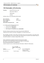
Page 6: ...r Directive 2000 14 EC Internal production control as per article 14 paragraph 2 in connection with annex V This declaration only refers to the machine in the state in which it has been placed on the...

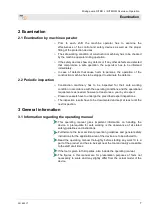
Page 7: ...ons and the operational requirements as needed however at least once a year by an expert Pressure vessels have to undergo the prescribed expert inspections The inspection results have to be documented...

Page 8: ...The operating manual is divided into 2 books Part 1 Safety General safety instructions mixing pumps feed pumps Article number 00 17 27 09 Part 2 Overview operation service and spare parts lists this...

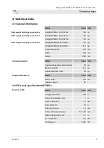
Page 9: ...MO M 00 06 49 61 94 5 Kg Length with pump 900 mm Width 600 mm Height 1380 mm Individual weights Detail Value Unit Undercarriage with control cabinet 60 kg Motor with grille 31 5 kg Hopper with pump un...

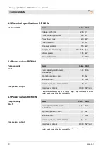
Page 10: ...d capacity continuously controllable 2 14 l min Operating pressure max 20 bar Grain size max 2 mm Feed range max at 25 mm 20 m Compressor output 0 080 Nm min reference value depending on conveying hei...

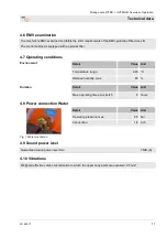
Page 11: ...perating conditions Environment Detail Value Unit Temperature range 2 45 C Relative humidity max 80 Duration Detail Value Unit Max operating time at a stretch 8 hours 4 8 Power connection Water Fig 1...

Page 12: ...lowing details can be found on the name plate Manufacturer Type Year of manufacture Machine number Permissible operating pressure 5 2 Quality Control sticker Fig 4 Quality Control sticker The followin...

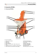
Page 13: ...astic side panel 5 Water inlet at mixing tube rubber mixing section 6 Wheel 7 Compressed air from air compressor to spraying gun 8 Water inlet water connection from water supply 9 Mortar pressure gaug...

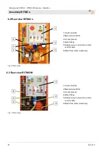
Page 14: ...ain terminal 230V 3 Air compressor 4 Water fitting 5 Dummy plug connection remote control cable 6 Water flow meter water tap 6 3 Rear view RITMO M Fig 7 Rear view 1 Control cabinet 2 Main terminal 230...

Page 15: ...xing pumps PFT RTIMO L and RITMO M consist of the following main components Mixing tube with material container vibrating unit RITMO L pump and gear motor The gear motor with tilt flange can also be r...

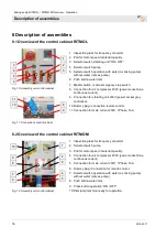
Page 16: ...power socket blue continuous current 9 Connection for vibrating unit 230V power socket grey controlled 10 Dummy plug connection remote control 11 Connection for main current 230V 1Phase 16A 8 2 Overv...

Page 17: ...ON OFF 8 Connection pressure control 9 Pressure switch air switches the machine ON OFF 8 4 Overview water fitting RITMO L RITMO M 1 2 3 4 5 6 7 Fig 14 Water fitting 1 Water flow meter 2 Pressure reduc...

Page 18: ...17 Operating modes pump motor The pump motor has three operating modes Selector switch position 0 The machine is switched off Selector switch right toggle The machine starts when the main switch is sw...

Page 19: ...plings Art No 00021103 Fig 22 PVC fabric hose NW 9x3mm 15m with EWO couplings V M part Art No 00008521 PVC fabric hose NW 9x3mm 5m with EWO couplings V M part Art No 00077240 PVC fabric hose NW 9x3mm...

Page 20: ...ssure 1 bar Maximum media and ambient temperature 75 C Assembly position as desired preferable vertical 13 2 Intended purpose solenoid valve Scope of application Solenoid valves for liquid and gaseous...

Page 21: ...ed purpose air compressor The tool is conceptualised and designed exclusively for the purpose of use specified here Attention The air compressor is intended exclusively for the generation of compresse...

Page 22: ...essor complies with the national and international safety regulations and can therefore also be used in damp rooms and or outdoors Areas with clean and dry air should be preferred Ensure that the devi...

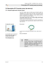
Page 23: ...ed by means of water supply from a water reservoir by the PFT booster pump A flow pressure of at least 2 5 bar with the machine in operation on the construction side is guaranteed by means of suction...

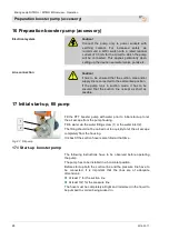
Page 24: ...as possible 17 Initial start up fill pump Fig 27 Fill pump Fill the PFT booster pump with water prior to initial start up to let the air escape from the pump housing Fill in water via the water fillin...

Page 25: ...couple of seconds If the pump does not deliver after a brief period this might be due to the following reasons There is still air in the pump and it has to be vented completely once again The suction...

Page 26: ...form a constructive unit with the machine Non compliance does not only cause loss of guarantee but also bad mortar quality is to be expected 19 2 Flowability Flow characteristics RITMO M NOTE The pump...

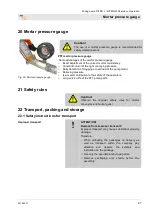
Page 27: ...r Relieving pressure Is a major contribution to the safety of the operators Long service life of the PFT pump parts 21 Safety rules Caution Observe the regional safety rules for mortar conveyors and m...

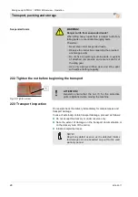
Page 28: ...ar and sling gear with sufficient lifting capacity 22 2 Tighten the nut before beginning the transport Fig 30 Tighten screw ATTENTION Generally ensure that the nut 1 for the protective grille is tight...

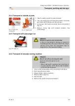
Page 29: ...ANGER Danger of injury by unsecured loads In case of road transport all persons involved in the loading process are responsible for the proper securing of the load The responsible driver is responsibl...

Page 30: ...aterials according to type and size and reuse or recycle ATTENTION Environmental damage due to wrong disposal Packaging materials are valuable raw materials and in many cases they can be reused or rec...

Page 31: ...use permanent hearing deficiencies At close range of the machine 78 dB A can be exceeded due to operational conditions Close range is a distance of less than 5 metres to the machine 25 Preparing the m...

Page 32: ...n of frequency converters 2 Interrupt the control circuit by removing the plugs 2 from the control cabinet 3 Remove connector Air compressor 3 from control cabinet WARNING Danger to life from rotating...

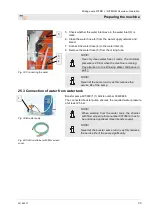
Page 33: ...running Pay attention to the Drinking Water Ordinance in part 1 NOTE Never let the pump run dry as this reduces the service life of the pump 25 3 Connection of water from water tank Fig 39 Booster pum...

Page 34: ...water supply button 2 Fig 43 as long as no air bubbles are to be seen in the water flow meter 3 any longer 5 Adjust the expected amount of water at the needle valve 4 Evident with the ball in the insp...

Page 35: ...again 4 Press the water supply button 2 Fig 46 as long as no air bubbles are to be seen in the water flow meter 3 any longer 5 Adjust the expected amount of water at the needle valve 4 Evident with t...

Page 36: ...protection Warning Health hazard caused by dust In the long term inhaled dust can lead to lung damage or have other adverse health effects NOTE The machine operator or the person working in the dusty...

Page 37: ...be Article number 20104301 Consistency test tube 25m piece 31 2 Start RITMO L in flying mode 2 4 3 Fig 51 Switching on 1 Close the control circuit by inserting the plug 1 in the control cabinet 2 Turn...

Page 38: ...ctions of rotation of the pump motor clockwise 5 Check material consistency at the consistency test tube 6 Switch off the machine at selector switch 4 centre position 7 Remove consistency test tube an...

Page 39: ...re is pressure on the mortar hoses check mortar pressure gauge The mix could burst out under pressure and result in serious injuries especially injuries to the eyes Torn off hoses can beat about and i...

Page 40: ...he spraying gun 2 at the mortar hose 4 34 3 Switch on air compressor Fig 58 Switch on air compressor 1 Insert the connector Air compressor 1 into the blue Schuko socket outlet 2 NOTE This small compre...

Page 41: ...ow characteristics If 15 bar or 20 bar operating pressure are exceeded the hose length must be reduced 35 1 Open the air tap at the spraying gun Fig 61 Switching on Fig 62 Opening the air tap 1 Turn t...

Page 42: ...system and mortar hoses depending on the setting time of the material and the length of the interruption pay attention to outside temperature The guidelines of the material manufacturers have to be ob...

Page 43: ...es to eyes and face Attention residual pressure 36 Remote control 36 1 Working with the remote control Fig 67 Remote control 1 Remove the dummy plug from the control cabinet and connect remote control...

Page 44: ...72 Pasty material 4 Turn the selector switch 3 clockwise to the Without water position 5 Turn poti 4 for motor speed material quantity to position 3 adjust as required 6 Turn the selector switch 5 di...

Page 45: ...rsons in the danger zone anymore 9 Check the system before reactivation and ensure that all safety equipment is installed and functional 39 Action in case of water outage NOTE With the help of a strai...

Page 46: ...if the mortar pressure has lowered to 0 bar If required relieve the mortar pressure by lightly loosening the screws 2 In doing so cover the work area with film 3 Firmly tighten the screws 2 again 40 3...

Page 47: ...O M starts again as soon as the air tap at the spray gun is opened again NOTE In case of a longer power cut the RITMO M and the material hoses have to be cleaned immediately 41 Work on troubleshooting...

Page 48: ...fety Personal protective equipment The following protective equipment has to be worn for all maintenance work Protective clothing Protective goggles protective gloves safety shoes ear protection Perso...

Page 49: ...rator Machine does not start Material Too much thickened material in hopper or mixing section Empty half of the hopper and start again Operator Excessively dry material in pump part Run the machine in...

Page 50: ...tar flow ceases air bubbles Bad mixture in mixing tube Add more water Operator Material is clumped and narrows the mixing tube inlet Add more water or clean agitator or replace Operator Material in mi...

Page 51: ...ying hoses for several reasons This means that the material to be conveyed remains stuck in the conveying hoses and cannot be pumped to the hose end 42 1 Removal of clogging in hoses signs for cloggin...

Page 52: ...cularly to the eyes Persons commissioned with the cleaning of clogged hoses have to wear personal protective equipment protective goggles gloves for safety reasons and to position themselves in such a...

Page 53: ...and face Therefore Always wear protective goggles Always position yourself in such a way that you are not hit by the mortar being discharged 1 Slightly loosen both screws 2 at the tie rod so that the...

Page 54: ...adjust as required 5 Turn the selector switch 1 clockwise 6 The RITMO L starts again as soon as the air tap at the spray gun is opened again 43 4 Switch machine back on after blockage has been cleared...

Page 55: ...and before longer breaks 44 2 Check mortar pressure RITMO L 3 4 4 Fig 86 Mortar pressure to 0 bar Switching off the machine 1 Turn the selector switch 1 to the Null position towards the left centre po...

Page 56: ...opening machine parts they can open in an uncontrolled manner and injure the operator Open machine only when the pressure is at 0 bar NOTE Mortar hoses and spraying device have to be cleaned immediate...

Page 57: ...5 Loosen the ring screw 6 and pull the air nozzle tube 7 out of the spray head 6 Open the water extraction valve Pos 2 Fig 88 until the sponge ball exits the spraying device 7 In case of strong soilin...

Page 58: ...ket housing with the protective cover 3 protection from moisture Fig 92 Remove the agitator 3 Remove the mixing shaft 4 and clean it 4 Cleaning the mixing zone with a spatula 44 8 Insert the mixing tu...

Page 59: ...tilt backwards with the motor 11 Remove the mixing tube cleaner with the cleaner shaft from the material container 44 10 Cleaning mixing tube RITMO M 3 2 Fig 96 Cleaning RITMO M 1 Close motor flange...

Page 60: ...ontainer and clean it 5 Insert and attach the rubber mixing section and pump unit after cleaning 6 Ensure correct position of the parts 44 12 Insert agitator Fig 99 Rotor position Fig 100 Drive dog po...

Page 61: ...e the pump unit 2 with mortar pressure gauge and clean it 4 Insert new rotor and stator or the cleaned pump unit and tighten nuts NOTE Assembled pump rotor in stator are stored for a few days only as...

Page 62: ...ollowing steps are to be carried out if the machine stands still in case of risk of frost Fig 105 Disconnect water supply 1 Remove the water hose 1 from the water inlet 2 Remove the water hose 2 from...

Page 63: ...1 7 Turn the main switch 2 to position 0 48 3 Blow dry water fitting RITMO M Fig 110 Blow dry water fitting 1 Insert the connector Air compressor into the blue socket outlet 2 Press the green push but...

Page 64: ...111 Remove connection cable DANGER Danger of death from electric current There is danger to life if you come in contact with live parts Activated electrical components can carry out uncontrolled move...

Page 65: ...ntervals have to be shortened according to the actual signs of wear Should you have any queries regarding maintenance works and intervals contact the manufacturer see page 2 for service addresses NOTE...

Page 66: ...valve 1 4 bar at maximum flow Needle valve 1 opened completely 50 3 Check pressure switch 50 4 Pressure switch water Fig 115 Pressure switch If faults occur increasingly replace the water pressure sw...

Page 67: ...eed 45 C 7 It is essential to store the compressor dry and to avoid the condensate through water vapour 8 It is prohibited to use the machine in explosive atmosphere High temperatures are generated on...

Page 68: ...mpressed air 50 7 Actions after completed maintenance 1 After finishing the maintenance works and prior to switching on the machine the following steps have to be carried out 2 Check all previously lo...

Page 69: ...Therefore Prior to starting the works ensure that there is sufficient space Carefully handle components with sharp edges Ensure order and cleanliness at the working place Loose components and tools on...

Page 70: ...materials and dispose off in an environment friendly way 52 Disposal If no agreement for the recovery or the disposal was made recycle the disassembled components Scrap metals Recycle plastic element...

Page 71: ...Mixing pump RITMO L RITMO M Overview Operation Disposal 2016 02 17 71...

Page 72: ...x the air 40 Connect mortar hose 39 Connecting the power supply 230V 32 Connecting the spraying gun 40 Connecting the water supply 32 Connection Mortar hose 18 Connection of water from water tank 33 C...

Page 73: ...1 Operating manual 7 Operating modes 18 Operation 30 Overview Air compressor DT4 8 230 V 17 Overview of the control cabinet RITMO L 16 Overview of the control cabinet RITMO M 16 Overview RITMO L 13 Ov...

Page 74: ...h machine back on after blockage has been cleared RITMO L 54 Switch machine back on after blockage has been cleared RITMO M 54 Switch off air compressor 43 Switch on air compressor 40 Switching off po...

Page 75: ...Mixing pump RITMO L RITMO M Overview Operation Notes 2016 02 17 75 54 Notes...

Page 76: ...tion 76 2016 02 17 THE FLOW OF PRODUCTIVITY Knauf PFT GmbH Co KG P O Box no 60 97343 Iphofen Einersheimer Stra e 53 97346 Iphofen Germany Phone 49 9323 31 760 Fax 49 9323 31 770 Technical hotline 49 9...

Reviews: