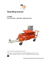
CAYMAN Part 2 Overview – Operation - Spare parts lists
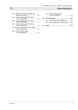
Table of Contents
2017-03-22
3
1
EC Declaration of Conformity ..................... 6
2
Examination .................................................. 7
2.1
Examination by machine operator ....... 7
2.2
Periodic inspection .............................. 7
3
General information ..................................... 8
3.1
Information regarding the operating
manual ................................................. 8
3.2
Keep the manual for future
reference .............................................. 8
3.3
Division ................................................ 8
4
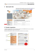
Spare parts lists ........................................... 9
5
Periodic inspections .................................... 9
6
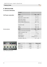
Technical data ............................................ 10
6.1
General information ........................... 10
6.2
Power connection .............................. 10
6.3
Operating conditions .......................... 11
6.4
Power values ..................................... 11
6.5
Sound power level ............................. 11
6.6
Vibrations ........................................... 11
7
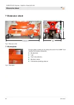
Dimension sheet ........................................ 12
7.1
Name plate ........................................ 12
8
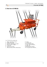
Overview CAYMAN .................................... 13
9
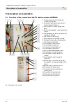
Description of assemblies ........................ 14
9.1
Overview of the control box with FU
Article number 00250808 .................. 14
9.2
Overview of control box article
number 00280799 ............................. 15
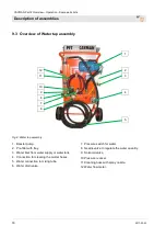
9.3
Overview of Water tap assembly ....... 16
10
Operating modes ....................................... 17
10.1
Selector switch for operating modes . 17
11
Intended use control panel ....................... 18
11.1
Intended purpose flow meter ............. 18
11.2
Intended purpose control panel ......... 19
11.3
Intended purpose solenoid valve ....... 19
12
Description Booster pump ........................ 20
12.1
Scope of application booster pump .... 20
12.2
Intended use ...................................... 20
13
Work flow .................................................... 21
13.1
Functional description ........................ 21
14
Basic equipment ......................................... 21
15
Material: ....................................................... 22
15.1
Flowability / Flow characteristic ......... 22
16
Mortar pressure gauge .............................. 22
17
Safety rules ................................................. 22
18
Transport, packing and storage................ 23
18.1
Safety instruction for transport ........... 23
18.2
Remove the complete pump unit ....... 23
18.3
Transport inspection ........................... 24
18.4
Transport ............................................ 24
18.5
Transport by car or truck .................... 25
18.6
Transport of already running
machine .............................................. 25
19
Packaging .................................................... 25
20
Operation ..................................................... 26
20.1
Safety ................................................. 26
21
Machine preparation .................................. 27
21.1
Positioning machine ........................... 27
21.2
Pull pump unit from chassis ............... 27
21.3
Connection of the machine FU
00248894 to the power supply ........... 28
21.4
Check the individual connectors ........ 28
21.5
Connection of the machine
00443371 to the power supply ........... 29
21.6
Check the individual connectors ........ 29
21.7
Connecting the water supply .............. 30
21.8
Water from water tank ........................ 30
22
Switching on ............................................... 31
22.1
Main switch......................................... 31
22.2
Pre-setting the water flow rate ........... 31
23
Mortar pressure gauge .............................. 32
Summary of Contents for 00 24 88 94
Page 83: ...CAYMAN Part 2 Overview Operation Spare parts lists Circuit diagrams 2017 03 22 83 ...
Page 84: ...CAYMAN Part 2 Overview Operation Spare parts lists Circuit diagrams 84 2017 03 22 ...
Page 85: ...CAYMAN Part 2 Overview Operation Spare parts lists Circuit diagrams 2017 03 22 85 ...
Page 86: ...CAYMAN Part 2 Overview Operation Spare parts lists Circuit diagrams 86 2017 03 22 ...
Page 87: ...CAYMAN Part 2 Overview Operation Spare parts lists Circuit diagrams 2017 03 22 87 ...
Page 88: ...CAYMAN Part 2 Overview Operation Spare parts lists Circuit diagrams 88 2017 03 22 ...
Page 89: ...CAYMAN Part 2 Overview Operation Spare parts lists Circuit diagrams 2017 03 22 89 ...
Page 90: ...CAYMAN Part 2 Overview Operation Spare parts lists Circuit diagrams 90 2017 03 22 ...
Page 91: ...CAYMAN Part 2 Overview Operation Spare parts lists Circuit diagrams 2017 03 22 91 ...
Page 93: ...CAYMAN Part 2 Overview Operation Spare parts lists Circuit diagrams 2017 03 22 93 ...
Page 94: ...CAYMAN Part 2 Overview Operation Spare parts lists Circuit diagrams 94 2017 03 22 ...
Page 95: ...CAYMAN Part 2 Overview Operation Spare parts lists Circuit diagrams 2017 03 22 95 ...
Page 99: ...CAYMAN Part 2 Overview Operation Spare parts lists 2017 03 22 99 ...

