background image


CAYMAN Part 2 Overview – Operation - Spare parts lists 


Spare parts drawing / spare parts list 


66 


2017-03-22


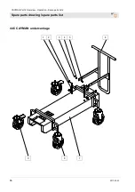
44.5 CAYMAN undercarriage 


Summary of Contents for 00 24 88 94

Page 1: ...arts lists Article number of the operating manual 00 59 79 01 Article number of the parts list machine 00 24 88 94 CAYMAN with frequency converter Article number of the parts list machine 00 44 33 71 CAYMAN without frequency converter Read the operating manual prior to starting any work ...

Page 2: ...2017 03 22 Knauf PFT GmbH Co KG P O Box no 60 97343 Iphofen Einersheimer Straße 53 97346 Iphofen Germany Phone 49 9323 31 760 Fax 49 9323 31 770 Technical hotline 49 9323 31 1818 info pft net www pft net ...

Page 3: ... meter 18 11 2 Intended purpose control panel 19 11 3 Intended purpose solenoid valve 19 12 Description Booster pump 20 12 1 Scope of application booster pump 20 12 2 Intended use 20 13 Work flow 21 13 1 Functional description 21 14 Basic equipment 21 15 Material 22 15 1 Flowability Flow characteristic 22 16 Mortar pressure gauge 22 17 Safety rules 22 18 Transport packing and storage 23 18 1 Safet...

Page 4: ... 43 35 4 Danger when there is overpressure in mortar hose 44 35 5 Release the pump 44 35 6 Blockage cannot be cleared 45 35 7 Interruption in conveying 45 36 Rest 45 37 End of work clean machine 46 37 1 Secure against restarting 46 37 2 Empty the machine FU Machine 46 37 3 Disconnect the mortar hoses 46 37 4 Cleaning the mortar hoses 47 37 5 Cleaning the mixer 47 37 6 Cleaning the pump and pump co...

Page 5: ...250808 70 44 8 Control cabinet with FU Article number 00250808 72 44 9 Control cabinet with FU Article number 00250808 74 44 10 Control cabinet without FU Article number 00280799 76 44 11 Control cabinet article number 00280799 78 44 12 Control cabinet article number 00280799 80 45 Circuit diagrams 82 45 1 Circuit diagrams CAYMAN FU 82 45 2 Circuit diagrams CAYMAN 400 V 92 46 Index 96 ...

Page 6: ...door Directive 2000 14 EC Internal production control as per article 14 paragraph 2 in connection with annex V This declaration only refers to the machine in the state in which it has been placed on the market Parts subsequently added by the user and or subsequent interventions are not covered This declaration ceases to be valid if the product is converted or changed without consent Person authori...

Page 7: ...fects or if any other defects are detected that compromise a safe operation the supervisor has to be informed immediately In case of defects that cause harm to persons the operation of the construction machine has to be stopped to eliminate the defects 2 2 Periodic inspection Construction machinery has to be inspected for their safe working condition in accordance with the operating conditions and...

Page 8: ... accessible to the staff at all times If the tool is given to third parties also include the operating manual The figures in this manual are for presentation purposes of facts not necessarily to scale and may slightly differ from the actual model of the device 3 2 Keep the manual for future reference The operating manual has to be available during the whole service life of the product 3 3 Division...

Page 9: ...the PFT machines can be found on the internet in the business login at www pft eu 5 Periodic inspections Inspection recommendations for the annual expert inspection of the CAYMAN which is to be conducted in accordance with BGR 183 can be found in this section http www pft de www de information_service recurrent_checks recurrent_checks php 1 2 3 ...

Page 10: ...26 A Power input 13 kW CEE connection 5 x 32 A Fuse protection At least 3 x 25 A Connection cable min 5 x 6 mm Fig 1 Motor protection switch Detail Power Setting value Pump motor 7 5kW 15 A Mixing motor 4 0kW 8 A Water pump 1 1kW 2 7 A Detail Value Unit Cmpl weight 435 kg Weight mixer chassis approx 195 kg Weight pump approx 140 Kg Weight caddy approx 100 kg Overall length extended pump 2615 mm Tr...

Page 11: ... 80 Duration Detail Value Unit Max operating time at a stretch 8 hours 6 4 Power values Pump capacity Mixer capacity Detail Value Unit Pump capacity approx 100 l min Operating pressure max 25 bar Feed range max at 50mmØ 100 m reference value depending on conveying height pump condition and version mortar quality composition and consistency 6 5 Sound power level Guaranteed sound power level LWA 95d...

Page 12: ... 22 7 Dimension sheet Fig 3 Dimension sheet 7 1 Name plate Fig 4 Name plate The type plate is located in the mixing tube and in the CADDY and includes the following information Manufacturer Type Year of manufacture Machine number Permissible operating pressure 1900 2615 855 895 ...

Page 13: ...e assembly groups 1 Mortar outlet flange in mixer 2 Rubber mixing tube 3 Protective grille with sack opener 4 Booster pump in CADDY 5 Control box 6 Gear motor for mixer 7 Motor protection handle slider handle 8 Castor 9 Undercarriage 10 Gear motor for pump 11 Pump material container 12 Pump unit 13 Mortar pressure gauge 14 Connection for mortar hose ...

Page 14: ...et 7 Step switch for six operation modes 8 Release the pump reverse operation 9 Pushbutton for lamp test 10 Control lamp system STOP 11 Control lamp no material 12 Connection to main terminal 13 Control lamp motor failure 14 Push button EMERGENCY OFF 15 Control lamp no water pressure 16 Control lamp change direction of rotation 17 Control lamp machine ready for operation 18 Dummy plug connection d...

Page 15: ...o material 7 Control lamp change direction of rotation 8 Control lamp motor failure 9 Connection wet sensor wet sensor in pump material container 10 Push button EMERGENCY OFF 11 Dummy connector Connection for remote control cable 12 Control lamp system STOP 13 Control lamp no water pressure 14 Release the pump reverse operation 15 Dummy plug connection dry sensor dry sensor in the material hopper ...

Page 16: ...pump 2 Pre filter with tray 3 Water inlet from water supply or water tank 4 Connection for cleaning the mortar hoses 5 Water connection to mixing tube 6 Water drain valve 7 Pressure switch for water 8 Needle valve to regulate the water quantity 9 Solenoid valve 10 Pressure reducer 11 Cleaning hose with spray nozzle 12 Water flow meter 1 2 3 4 5 12 11 10 9 8 7 6 ...

Page 17: ... button lamp test Fig 10 Selector switch water pump Main switch ON control voltage ON Selector switch water pump Manual Water pump is in operation For cleaning the hoses or for water extraction by water extraction valve The water quantity evident on the sight glass of the water flow meter at the needle valve can be adjusted Fig 11 Selector switch mixer Main switch ON control voltage ON Selector sw...

Page 18: ... container NOTE Water factor must be set at prescribed value Fig 14 Release selector switch pump Main switch ON control voltage ON release Selector switch pump Press blue push button Release pump The pump motor rotates in the opposite direction and relieves the pressure in the pump Fig 15 Run selector switch mixer empty Main switch ON control voltage ON run Selector switch mixer empty FU Another p...

Page 19: ...ation Solenoid valves for liquid and gaseous media aggressive or neutral can be used different temperature and pressure ranges Type 6213 is a 2 2 way solenoid valve with straight passage normally closed with a permanently coupled membrane system It operates from 0 bar and can be used universally for liquids A minimum pressure differential of 0 5 bar is required for the valve to fully open WARNING ...

Page 20: ...age and irrigation The constant water supply of the PFT machine technology is automatically ensured by means of water supply from a water reservoir by the PFT booster pump A flow pressure of at least 2 5 bar with the machine in operation on the construction side is guaranteed by means of suction from the water reservoir 12 2 Intended use Attention The booster pump is recommended only for pumping o...

Page 21: ...g tube and is forwarded from there at up to 100 l min to processing plant The control box with programmable logic control PLC regulates the interplay of the components in the automatic mode For the run in of the system and even the cleaning after finishing the work all functions can also be controlled manually at the control box For a more secure functioning of the system an appropriate water pres...

Page 22: ...mpatible with each other and form a constructive unit with the machine Non compliance does not only cause loss of guarantee but also bad mortar quality is to be expected 16 Mortar pressure gauge Caution The use of a mortar pressure gauge is recommended for safety related reasons Fig 16 Mortar pressure gauge PFT mortar pressure gauge Some advantages of the mortar pressure gauge Exact adjustment of ...

Page 23: ... to life from falling parts or uncontrolled swinging parts Therefore Never step under suspended loads Observe the instructions regarding the provided anchorage points Do not fix at projecting machine parts or eyelets of attached components and ensure safe fit of the sling gear Use only approved lifting gear and sling gear with sufficient lifting capacity When ropes and chains are used in construct...

Page 24: ...sport Fig 18 Truck transport Truck transport 1 Pay attention that the turning bolts 1 for securing the pump are engaged 2 Lock the castors 2 3 Secure lose parts or remove them 4 The material container of the mixer must be completely empty and clean 5 Check whether all supply lines and hoses are decoupled 6 Lock control box doors of CADDY Anchor points Fig 19 Crane transport Crane transport Anchor ...

Page 25: ...gauge 1 Carry out the following steps before beginning the transport 2 First unplug the mains cable 3 Unplug all other cable connections and water hoses 4 Start transport 5 In case of transport by crane remove the loose parts 19 Packaging For packaging The individual packages have to be packed in accordance with the transport conditions to be expected Only environmentally friendly materials were u...

Page 26: ...tective equipment that is to be worn when effective particular jobs will be pointed out separately in the warning instructions of this chapter Basic information WARNING Danger of injury due to incorrect operation Improper operation may lead to serious damage to persons or property Therefore Carry out all operating steps according to the instructions in this user manual Prior to starting your work ...

Page 27: ... preparation and operation the protective grids 1 must not be removed Never reach into the running machine Fig 21 Lockable castor Put up the PFT CAYMAN on a stable even surface and secure against unwanted movements Put up the machine in such a way that it cannot be hit by falling objects Lock the castors 2 of the machine The operating elements have to be freely accessible 21 2 Pull pump unit from ...

Page 28: ...e required for the operation of frequency converters 21 4 Check the individual connectors Fig 25 Connection of mixer motor Fig 26 Connection of pump motor WARNING Danger to life from rotating parts Improper operation may lead to serious damage to persons or property The respective drive motors must be operated only with the control box of the machine Using other or external power sources is forbid...

Page 29: ...Check the individual connectors Fig 29 Connection of mixer motor Fig 30 Connection of pump motor WARNING Danger to life from rotating parts Improper operation may lead to serious damage to persons or property The respective drive motors must be operated only with the control box of the machine Using other or external power sources is forbidden for safety reasons All the connections should be made ...

Page 30: ...the water hose 5 Remove the water hose 2 from the mixing tube and put it in the pump container 6 Check whether all outlet valves and the shut off valves on the water fitting are closed 7 Open water cock for water inlet NOTE Use only clean water free of solids The minimum pressure is 2 5 bar when the machine is running 21 8 Water from water tank Fig 34 Booster pump Fig 35 Suction strainer complete ...

Page 31: ...eft it can be switched back to position 0 but is blocked for the right position 3 Press the green push button operation ON 3 Fig 37 Selector switch water pump 4 Switch the selector switch 4 to the stage 1 5 Press the water supply button 5 22 2 Pre setting the water flow rate Fig 38 Regulator valve 1 Keep the water supply button 5 Fig 37 pressed till no air bubbles are to be seen in the water flow ...

Page 32: ... 6 Fig 41 Selector switch Manual pump 4 Turn the Selector switch 7 to position 3 Manual pump 5 Empty the pump container till a little residual water remains NOTE Never let the pump run dry as this reduces the service life of the pump 23 Mortar pressure gauge Fig 42 Mortar pressure gauge DANGER Operating pressure too high Machine parts can open in an uncontrolled manner and injure the operator Ther...

Page 33: ...uipment the machine can be fed with bagged goods with the delivery hood or the injection hood DANGER Risk of injury at the sack opener The sharp edges of the sack opener pose a risk of injury Wear safety gloves 26 Monitoring the machine DANGER Access by unauthorised persons The machine must be operated only if monitored 27 Putting the machine into operation 27 1 Risk of injury from discharged mort...

Page 34: ...ose couplings as long as there is pressure on the mortar hoses check mortar pressure gauge The mix could burst out under pressure and result in serious injuries especially injuries to the eyes NOTE The possible conveying distance depends mainly on the flowability of the mortar Heavy sharp grained mortar has poor flow characteristics Runny materials have good flow characteristics If 25 bar operatin...

Page 35: ...nt from the adjacent table 28 2 Optimum consistency Fig 49 Correct consistency 1 Correct the amount of water at the regulator valve 1 for optimum consistency 2 The amount of water is evident on the floater 2 of water flow meter 29 Sensor controller 29 1 Dry sensor Fig 50 Dry sensor 1 The material level in the material container of the mixer is monitored by a dry level sensor 1 2 If the dry level s...

Page 36: ...with the remote control Fig 52 Connecting the remote control 1 Remove dummy plug 1 from control box 2 Insert plug 2 from the cable drum of remote control Fig 53 Remote control 3 The automatic mode can be switched on or off with the push button 3 on the remote control Cable drum with remote control 50 m Article number 00 02 22 60 31 Interruption of work NOTE Always observe the setting time of the m...

Page 37: ...mergency vehicles 7 If the severity of the emergency permits inform the competent authorities 8 Assign specialised personnel with the troubleshooting 9 Check the system before reactivation and ensure that all safety equipment is installed and functional After the rescue operations WARNING Danger to life from premature reactivation On reactivation there is danger to life for all persons in the dang...

Page 38: ...2 Control lamps 7 8 6 5 4 1 2 3 Fig 56 Fault displays Pos Light signal Description 1 red control lamp Lights up when the motor protection switch has been triggered Check motor protection switch 2 Yellow control lamp Control lamp system STOP machine is switched off over the remote control 3 Yellow control lamp Control lamp no material 4 EMERGENCY STOP switch Blinks when EMERGENCY OFF button is pres...

Page 39: ...not be rectified by means of the following notes kindly contact the dealer NOTE The following fault table gives information on who is authorised to rectify the fault 34 5 Safety Personnel The work for rectification of faults described here can be carried out by the operator unless marked otherwise Some works must be carried out only by specially trained skilled personnel or exclusively by the manu...

Page 40: ... Manual automatic selector switch was not in the middle position while switching on Bring the selector switch in the middle position and switch on the control again Operator Control lamp Change direction of rotation lights up Change the direction of rotation at the main switch Check fuse or supply line Operator Micro fuses on the transformer faulty Replace micro fuses Service engineer Machine does...

Page 41: ...he manual automatic switch at zero and turn back on Automatic Operator Defective capacitive wet sensor Replace defective component Service engineer Solenoid valve does not open Solenoid valve contaminated Dismount solenoid valve and clean Service engineer Solenoid valve defective Change solenoid valve Service engineer Water is running on in mixer standby Solenoid valve contaminated Dismount soleno...

Page 42: ...n the hose Operator PLC control program sequence Check the programme sequence Service engineer Very less material in the machine Level sensor Clean level sensor Operator Pump motor does not start Pump motor defective Replace the pump motor Service engineer Connection cable defective Change connection cable Service engineer Consistency variation Thick thin Water safety switch set incorrectly or def...

Page 43: ...sing pressure head blocking of pump running difficulties or blockage of the pump motor expansion and turning of the mortar hose no mortar discharge at hose end 35 2 Causes of blockages Highly worn mortar hoses work interruptions badly greased mortar hoses residual water in mortar hose clogging of the pressure flange strong tapering at the couplings kink in mortar hose Poorly pumpable and separated...

Page 44: ...lves in such a way that they cannot be hit by discharged material Other persons have to clear the area 35 5 Release the pump 2 1 3 Fig 58 Release the pump 1 Turn the Selector switch 1 to position 5 Release pump 2 Press the green push button control voltage operation ON 2 3 Press the blue push button 3 release pump and press until the pressure at the mortar pressure gauge has dropped to 0 bar Fig 5...

Page 45: ... out the material PFT rinsing hose art no 00113856 5 Wash in mortar hoses again Fig 61 Mortar pressure gauge DANGER Overpressure on the machine When opening machine parts they can open in an uncontrolled manner and injure the operator Open the mortar hoses only when the pressure has dropped to 0 bar 35 7 Interruption in conveying NOTE Avoid interruptions in conveying over a longer time as far as p...

Page 46: ...ork 1 Turn the selector switch 1 to position 6 empty the mixer 2 The mixer conveys material in the pump container till the pilot lamp No Material lights up 3 The machine switches off on its own NOTE Never let the pump run dry as this reduces the service life of the pump 37 3 Disconnect the mortar hoses 1 Fig 64 Mortar pressure to 0 bar 1 Check the mortar pressure gauge if the mortar pressure has l...

Page 47: ...ong soiling repeat this process 7 In case of different hose diameters the mortar hoses have to be cleaned separately with the matching sponge balls 37 5 Cleaning the mixer 1 4 1 Fig 67 Cleaning the mixer DANGER Danger to life from unauthorised restarting When working with the machine there is the risk that the energy supply is switched on without authorisation This poses a danger to life for the p...

Page 48: ...ump on the pressure flange and let the turning bolt 2 engage 3 A gap forms in the lower area 4 The water can escape from the pump material container Fig 70 Cleaning the pump container Water 5 Clean the pump container 3 of sticky material residues with the cleaning hose from the water fitting Fig 71 Locking the pump 6 Slightly raise the pump on the handle of pressure flange and open the turning bol...

Page 49: ...sidual water is pumped out of the pump in case of risk of frost also 37 7 Installing the cleaned mixing tube Fig 74 Installing the mixer NOTE While installing take care that you are clean and dry Pay attention to the correct fit of metering and mixing shaft Always keep the quick closures and seals clean Grease the bearing journal and connecting pieces of the mixing shaft 38 Action in case of power...

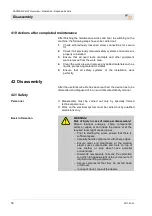
Page 50: ...e water hoses Fig 76 Remove the water hose Fig 77 Remove the water hose 1 Remove the water hose 1 from the water fitting 2 Remove the water hose 2 from the mixing tube 3 3 4 3 5 6 4 Fig 78 Water fitting 3 Open draining cocks 3 4 Open shut off valves 4 5 Loosen the water hose 5 from the water fitting 6 Unscrew the pre filter 6 so that the residual water can flow out of the filter and the booster pu...

Page 51: ...age Prior to starting the works ensure that there is enough space to carry out the works Ensure order and safety at the assembly site Loose components and tools on top of one another or lying about pose potential accident risks f components were removed ensure proper assembly and put back all fastening elements Electrical system Fig 82 Remove connection cable DANGER Danger of death from electric c...

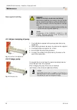
Page 52: ...1 Adjust clamping of pump Fig 83 Stator can be retightened 1 The CAYMAN is equipped with a pump system that can be retightened 2 If the pumping pressure decreases the stator can be adjusted 3 The supply pressure is approx 20 25 bar 4 Do not adjust the pump during operation 5 The lesser the voltage of the spiral casing the lesser is the wear of the spiral pump 41 2 Change pump Fig 84 Change pump Pu...

Page 53: ...se stacked components or components lying about can cause accidents If components were removed ensure proper assembly put back all fastening elements and observe torque indications for screws Electrical system DANGER Danger of death from electric current There is danger to life if you come in contact with electrical components Activated electrical components can carry out uncontrolled movements an...

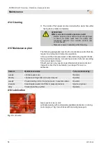
Page 54: ...creased wear is detected during regular checks the required maintenance intervals have to be shortened according to the actual signs of wear Should you have any queries regarding maintenance works and intervals contact the manufacturer see page 2 for service addresses Interval Maintenance work To be carried out by weekly Lubricate gear seal Operator Weekly Lubricate turning bolts and quick closure...

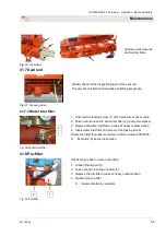
Page 55: ...1 of the pressure reducer valve 2 Take out and clean the water inlet filter 2 every two weeks 3 Replace the water inlet filter in case of heavy contamination 4 Insert water inlet filter and screw in the locking screw Water inlet filter for pressure reducer Article number 20156000 Execution by service technician 41 8 Pre filter 2 1 Fig 89 Pre filter Check the pre filter in water inlet daily 1 Loose...

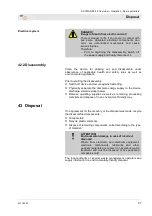
Page 56: ... to be dismantled and disposed of in an environmental friendly manner 42 1 Safety Personnel Disassembly must be carried out only by specially trained technical personnel Work on the electrical system must be carried out by qualified electricians only Basic information WARNING Risk of injury in case of improper disassembly Stored residual energies sharp components points or edges at and inside the ...

Page 57: ...nst restarting Physically separate the complete energy supply to the device discharge stored residual power Remove operating supplies as well as remaining processing materials and dispose of in an environment friendly way 43 Disposal If no agreement for the recovery or the disposal was made recycle the disassembled components Scrap metals Recycle plastic elements Dispose of remaining components so...

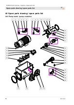
Page 58: ...parts lists Spare parts drawing spare parts list 58 2017 03 22 44 Spare parts drawing spare parts list 44 1 Pump motor pump container 1 2 3 4 5 6 7 8 9 10 11 12 13 33 32 31 30 14 10 15 16 17 18 19 20 21 22 23 24 25 26 27 28 29 38 37 36 35 34 ...

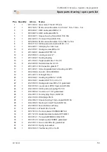
Page 59: ...ection glass R 1 17 1 20 14 40 21 Slide ring gasket set oil sealing unit ZP3 18 1 00 02 38 86 Hub D 35 for FERRO II 19 1 20 14 40 15 O Ring D 50 x 2 20 1 00 02 36 61 Sealing ring D53 5 x 12 5 T8 21 1 00 02 36 67 Gasket USIT 13 7 x 22 x 1 5 22 1 20 20 59 00 Hexagonal screw M12 x 50 galvanised 23 1 00 45 31 82 Level sensor KPS1 Cayman 42V 50Hz 24 2 20 43 09 00 Skintop screw coupling PG 13 5 25 1 20 ...

Page 60: ...CAYMAN Part 2 Overview Operation Spare parts lists Spare parts drawing spare parts list 60 2017 03 22 44 2 Pump unit 1 2 3 11 10 9 8 7 4 5 6 ...

Page 61: ...mp flange CAYMAN BETA II 4 1 00 02 10 25 ROTOR FERRO 5 1 00 51 26 85 Stator FERRO soft RAL2004 6 2 20 11 89 12 Clamping screw M16 x 630 galvanised for tie rod 20118910 7 2 20 20 99 21 Collar nut M16 galvanised 8 1 00 09 90 89 Manometer with plastic inlet housing 0 100 bar 1 pressure reducer VA 9 1 00 10 21 16 Pressure flange T Pump 2 RAL2004 10 1 20 17 21 03 Support plate for ZP 3 pump with carryi...

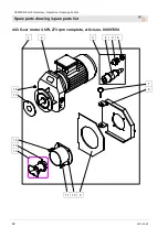
Page 62: ...CAYMAN Part 2 Overview Operation Spare parts lists Spare parts drawing spare parts list 62 2017 03 22 44 3 Gear motor 4 kW 273 rpm complete article no 00097094 1 2 3 4 5 6 11 10 9 16 15 14 13 12 7 8 ...

Page 63: ... 6 1 00 04 61 38 Reduction plastic M25x1 5 M20x1 5 7 1 20 10 10 10 Lynch pin D 4 5 with ring 8 1 00 04 79 50 Motor flange HM 106 2006 RAL 2004 9 1 00 04 79 35 Gasket of motor flange HM 106 10 1 20 10 29 05 Protective tube for drive dog 11 2 20 20 78 00 Hex screw M8 x 30 galvanised 12 1 20 10 29 11 Drive dog with round drogue system 25 mm bore HM 2 HM 200 13 1 20 20 96 03 Threaded pin with hexagon ...

Page 64: ...Part 2 Overview Operation Spare parts lists Spare parts drawing spare parts list 64 2017 03 22 44 4 Material container with rubber mixing tube 1 12 11 10 9 8 7 2 3 4 5 6 25 24 23 22 21 20 19 18 17 16 15 14 13 ...

Page 65: ...ng washer HM 11 1 20 20 93 14 Serrated washer A 8 4 galvanised 12 1 20 20 97 03 Cylinder screw with hexagon socket M8 x 30 galvanised 13 2 20 20 89 00 Safety nut M12 galvanised 14 1 20 54 55 06 Square external bearing 15 1 00 04 51 69 Flange bearing housing type FYT B 508M 16 1 00 04 51 44 Rubber gasket HM 6 17 1 00 58 14 22 Mortar outlet flange CAYMAN BETA II RAL2004 18 1 00 04 79 95 Rubber gaske...

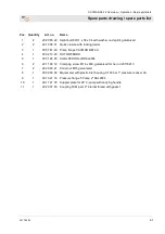
Page 66: ...CAYMAN Part 2 Overview Operation Spare parts lists Spare parts drawing spare parts list 66 2017 03 22 44 5 CAYMAN undercarriage 1 2 3 4 5 6 9 8 7 ...

Page 67: ...0 Lynch pin D 4 5 with ring 3 2 20 20 66 03 Safety capped nut M8 galvanised 4 2 20 20 93 13 Washer B 8 4 galvanised PACKING UNIT 10 PCS 5 2 20 20 63 23 Saucer head screw M8 x 25 galvanised 6 1 00 57 80 88 Transport handle CAYMAN BETA II 7 1 00 57 80 61 CAYMAN BETA II undercarriage 8 2 00 49 49 11 Castor 230 mm with steel rim 9 2 00 49 49 14 Stop castor 230 mm with steel rim ...

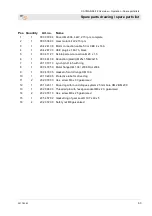
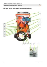
Page 68: ...Part 2 Overview Operation Spare parts lists Spare parts drawing spare parts list 68 2017 03 22 44 6 Spare parts drawing CADDY with water tap assembly 14 13 12 11 10 9 8 1 2 3 4 5 6 7 23 22 21 20 19 18 17 16 15 ...

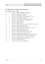
Page 69: ...3000 10 1 20 20 16 81 High pressure suction coupling 3 4 external thread with gasket 11 1 20 21 52 00 Shut off valve 1 2 without drain 12 1 00 00 21 97 Water hose air hose 3 4 x 6000mm 13 1 20 20 16 00 Geka coupling 3 4 sleeve PACKING UNIT 10 PCS 14 1 00 08 26 79 Pressure switch type BC 0 5 3 bar 15 3 00 04 04 28 Outlet valve control panel gun metal 16 1 00 01 99 13 Pressure gauge 0 16 bar 1 4 rea...

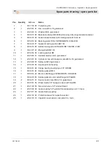
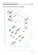
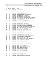
Page 70: ...CAYMAN Part 2 Overview Operation Spare parts lists Spare parts drawing spare parts list 70 2017 03 22 44 7 Control cabinet with FU Article number 00250808 ...

Page 71: ...79 Luminous element red 12 30V 20 1 00 18 63 75 Emergency stop shield in four languages 21 1 00 18 63 74 Emergency stop button M22 illuminated 21 2 00 05 38 40 Touch plate for pushbutton Green On M22 22 1 00 05 38 36 Contact element 1 opener M22 EK01 23 1 00 10 21 36 Control lamp LED 48V AC DC red 24 1 00 05 38 42 Touch plate for pressure switch black liquid M22 25 1 00 05 38 73 Transparent lamp i...

Page 72: ...on Spare parts lists Spare parts drawing spare parts list 72 2017 03 22 44 8 Control cabinet with FU Article number 00250808 1 2 3 4 Q2 Q3 Q4 Q5 Q6 K7 13 12 11 10 7 9 7 8 7 6 5 K2 K4 K10 K5 K9 K11 K3 K1 20 19 18 20 19 18 17 16 15 14 ...

Page 73: ...switch 10 16A PKZM 0 16 9 1 00 04 38 42 Motor protection switch 6 10A PKZM0 10 10 1 00 04 26 03 Motor protection switch 2 5 4A PKZM 0 4 11 1 00 04 63 79 Miniature circuit breaker C 0 5A 1 pin 12 2 00 08 31 38 Miniature circuit breaker C 4A 1 pin 13 1 20 41 93 10 Miniature circuit breaker B 16A 1 pin 14 3 20 44 81 20 Coupling relay 42 V 2 changer 15 1 00 26 28 73 Monitoring relay 16 1 00 08 42 25 A...

Page 74: ...YMAN Part 2 Overview Operation Spare parts lists Spare parts drawing spare parts list 74 2017 03 22 44 9 Control cabinet with FU Article number 00250808 1 2 3 4 5 6 7 1 OUTPUT INPUT 15 14 8 9 10 11 12 13 ...

Page 75: ...RAL7035 6 1 00 45 40 78 Door CAYMAN FC RAL7035 7 1 00 28 98 80 Filter fan 24 V DC for control box 8 1 20 43 20 01 Socket housing 10 pin HAN 10 E 9 1 20 43 22 00 Socket insert 10 pin HAN 10E 10 1 00 06 69 81 EMC cable gland M25 x 1 5 11 1 00 06 69 84 EMC counter nut M20 x 1 5 12 1 00 07 02 88 Strain relief for EMC cable gland galvanised M 25 x 1 5 13 1 00 14 74 84 Frequency converter V1000 7 5 KW 4...

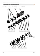
Page 76: ... 2 Overview Operation Spare parts lists Spare parts drawing spare parts list 76 2017 03 22 44 10 Control cabinet without FU Article number 00280799 1 2 3 4 2 5 14 13 10 9 12 9 11 9 10 9 8 7 6 17 16 14 16 14 16 15 ...

Page 77: ... hour counter 42 V 7 1 00 25 46 00 Miniature circuit breaker C 2 5A 1 pin 8 1 00 04 25 99 Motor protection switch 0 63 1A PKZM 0 1 9 4 00 02 14 01 Auxiliary contactor NHI 11 PKZO 10 2 00 04 26 02 Motor protection switch 10 16A PKZM 0 16 11 1 00 04 38 42 Motor protection switch 6 10A PKZM 0 10 12 1 00 04 26 03 Motor protection switch 2 5 4A PKZM 0 4 13 1 00 08 42 26 Air break contactor DIL M25 10 4...

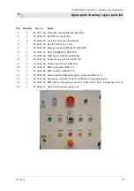
Page 78: ...ts lists Spare parts drawing spare parts list 78 2017 03 22 44 11 Control cabinet article number 00280799 21 22 18 7 11 10 21 20 19 18 17 21 23 18 21 20 17 19 21 19 18 19 18 1 2 3 4 5 6 7 7 8 9 21 20 18 21 16 15 14 6 13 4 7 12 20 17 21 21 19 18 ...

Page 79: ...r red luminous pushbutton 9 2 00 05 37 67 Hinge 180 10 1 00 41 35 82 Emergency stop emergency halt switch 11 1 00 18 63 75 Emergency stop shield in four languages 12 2 00 03 62 49 Lock double bit 13 1 00 05 38 43 Touch plate blue Reset 14 1 00 45 39 54 Door CAYMAN 15 1 00 05 38 31 Square switch protection membrane for double pushbutton 16 1 00 05 38 32 Double luminous pushbutton On Off 17 3 00 05 ...

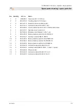
Page 80: ...CAYMAN Part 2 Overview Operation Spare parts lists Spare parts drawing spare parts list 80 2017 03 22 44 12 Control cabinet article number 00280799 1 2 3 4 5 6 7 8 9 17 16 15 14 10 11 12 13 19 18 ...

Page 81: ...ve cover 7 1 20 42 98 23 Sleeve housing 10 pin angled 10A 8 1 20 42 98 22 Pin insert 10 pin narrow 9 1 20 42 98 22 Pin insert 10 pin narrow 10 1 00 00 10 80 6 pin socket housing 11 1 20 42 84 05 Sleeve housing 6 pin 12 1 20 42 84 07 Pin insert 6 pin 13 1 20 42 84 08 Female insert 6 pin 14 2 00 04 11 41 Skintop screw coupling M16 x 1 5 15 2 00 04 11 43 Skintop counter nut M 16 x 1 5 16 1 00 04 11 2...

Page 82: ...CAYMAN Part 2 Overview Operation Spare parts lists Circuit diagrams 82 2017 03 22 45 Circuit diagrams 45 1 Circuit diagrams CAYMAN FU ...

Page 83: ...CAYMAN Part 2 Overview Operation Spare parts lists Circuit diagrams 2017 03 22 83 ...

Page 84: ...CAYMAN Part 2 Overview Operation Spare parts lists Circuit diagrams 84 2017 03 22 ...

Page 85: ...CAYMAN Part 2 Overview Operation Spare parts lists Circuit diagrams 2017 03 22 85 ...

Page 86: ...CAYMAN Part 2 Overview Operation Spare parts lists Circuit diagrams 86 2017 03 22 ...

Page 87: ...CAYMAN Part 2 Overview Operation Spare parts lists Circuit diagrams 2017 03 22 87 ...

Page 88: ...CAYMAN Part 2 Overview Operation Spare parts lists Circuit diagrams 88 2017 03 22 ...

Page 89: ...CAYMAN Part 2 Overview Operation Spare parts lists Circuit diagrams 2017 03 22 89 ...

Page 90: ...CAYMAN Part 2 Overview Operation Spare parts lists Circuit diagrams 90 2017 03 22 ...

Page 91: ...CAYMAN Part 2 Overview Operation Spare parts lists Circuit diagrams 2017 03 22 91 ...

Page 92: ...CAYMAN Part 2 Overview Operation Spare parts lists Circuit diagrams 92 2017 03 22 45 2 Circuit diagrams CAYMAN 400 V ...

Page 93: ...CAYMAN Part 2 Overview Operation Spare parts lists Circuit diagrams 2017 03 22 93 ...

Page 94: ...CAYMAN Part 2 Overview Operation Spare parts lists Circuit diagrams 94 2017 03 22 ...

Page 95: ...CAYMAN Part 2 Overview Operation Spare parts lists Circuit diagrams 2017 03 22 95 ...

Page 96: ...70 74 Control cabinet with FU Article number 00250808 72 Control cabinet without FU Article number 00280799 76 Control lamps 38 D Danger when there is overpressure in mortarhose 44 Description Booster pump 20 Description of assemblies 14 Dimension sheet 12 Disassembly 56 57 Disconnect the mortar hoses 46 Disposal 57 Dry sensor 35 E Earlier damage to the mortar hose 43 EC Declaration of Conformity ...

Page 97: ... Initial start up 39 installation 39 maintenance 53 Positioning machine 27 Potentiometer 35 Power connection 10 Power values 11 Pre filter 55 Pre setting the water flow rate 31 Pull pump unit from chassis 27 Pump motor pump container 58 Pump unit 60 Putting the machine into operation 33 R Reaction in the event of faults 38 Release the pump 44 Remote control 36 Remove the complete pump unit 23 Remo...

Page 98: ...ansport 23 24 Transport by car or truck 25 Transport inspection 24 Transport is at a standstill Blockage 43 Transport of alreadyrunning machine 25 V Vibrations 11 W Water inlet filter 55 Wet sensor 36 Work flow 21 Work on troubleshooting 38 Working with the remote control 36 ...

Page 99: ...CAYMAN Part 2 Overview Operation Spare parts lists 2017 03 22 99 ...

Page 100: ...s lists 100 2017 03 22 PFT THE FLOW OF PRODUCTIVITY Knauf PFT GmbH Co KG P O Box no 60 97343 Iphofen Einersheimer Straße 53 97346 Iphofen Germany Phone 49 9323 31 760 Fax 49 9323 31 770 Technical hotline 49 9323 31 1818 info pft net www pft net ...

Reviews: