background image

Mixing pump RITMO XL FC-230/400V / Part 2 Overview, operation and service

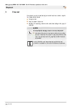
Disposal

8

Disposal

Provided no return or disposal agreements have been made, recycle

the disassembled parts:

Scrap metals.
Recycle plastic elements.
Dispose of remaining components, sorted according to the type of

material.

NOTE

Environmental damage due to incorrect disposal!

Electrical scrap and components, lubricants and other

process materials are subject to special guidelines and

may only be disposed of by approved waste disposal

specialists!

Local authorities and waste disposal specialists can
provide more details on the correct disposal of materials.

page 74 / 76

Summary of Contents for 00197821

Page 1: ...ce Item no of the operating manual 00235201 RITMO XL FC 230 400V 1 3 Ph 50 Hz Item no 00197821 RITMO XL FC 230 400V 1 3 Ph 50 Hz geothermal energy Item no 00231496 RITMO XL FC 230 400V 1 3 Ph 50 Hz wi...

Page 2: ...roduction of this document exploitation or communication of its contents are prohibited unless expressly autho rised Violations may lead to damage compensation All rights are reserved in the event of...

Page 3: ...ompressor and control box 23 4 4 3 Control box 23 4 4 4 Air compressor 24 4 4 5 Mortar pressure gauge 24 4 5 Connections of water and air 25 4 6 Operating modes 25 4 7 Voltage 230V 400V changing 26 4...

Page 4: ...es 62 6 Maintenance 65 6 1 Safety 65 6 1 1 Remove connection cable 66 6 2 Environmental protection 66 6 3 Maintenance plan 67 6 4 Maintenance work 67 6 4 1 Implementation by a service techni cian 67 6...

Page 5: ...al are for presentation purposes of facts not necessarily to scale and may slightly differ from the actual model of the device 1 2 Division The operating manual is divided into 2 books Part 1 Safety d...

Page 6: ...described Warning Death or serious injury may occur if you do not take the precautions described Caution Minor injury may occur if you do not take the precautions described Note Property damage may oc...

Page 7: ...2000 14 EC Internal production control as per article 14 paragraph 2 in connection with annex V This declaration only refers to the machine in the state in which it has been placed on the market Part...

Page 8: ...ral non flammable gases Maximum operating pressure initial pressure 16 bar After pressure infinitely adjustable from 1 5 to 6 bar Smallest possible initial pressure 2 5 bar Minimum pressure gradient i...

Page 9: ...Only use the flowmeter as intended Always adhere to the usage directives of the material manufacturer Strictly follow all instructions in this operating manual We accept no responsibility for damages...

Page 10: ...technically perfect condition as well as for its intended use and while taking into account the safety and hazard information in the operating manual In particular faults that can impair safety must b...

Page 11: ...d only in rooms where the hazard of a potentially explosive atmosphere is not given 1 8 5 3 Hot surfaces on the air compressor General information WARNING Risk of injury due to hot surface Surface tem...

Page 12: ...3 Dimension sheet in mm Detail Value Unit Empty weight approx 232 kg Length 1300 mm Width 700 mm Height 1510 mm Individual weights Detail Value Unit Pump motor with material hopper and pump 94 kg Chas...

Page 13: ...esignation Pump motor 6 05 kW 11 A Q2 Compressor 0 5 kW 3 3 A Q4 2 3 Operating conditions Environment Detail Value Unit Temperature range 2 45 C Relative humidity max 80 Duration Detail Value Unit Max...

Page 14: ...3 5 12 l min at 400 rpm Operating pressure maximum 30 bar Maximum grain size 3 mm Feed range max with 25 mm 30 m Feed range max with 35 mm 40 m Reference value depending on conveying height pump condi...

Page 15: ...ximum grain size 2 mm Feed range max with 25 mm 20 m Feed range max with 35 mm 30 m Reference value depending on conveying height pump condition and version mortar quality composition and consistency...

Page 16: ...e is danger to life from falling parts or uncontrolled swinging parts Therefore Never step under suspended loads Observe the instructions regarding the provided anchorage points Do not attach to proje...

Page 17: ...n accordance with the transport conditions to be expected Only environmentally friendly materials were used for the packaging The packaging should protect the individual components until the assembly...

Page 18: ...nchor points 1 for transport by crane Observe the following conditions The crane and lifting equipment have to be designed for the weight of the packages The operator has to be authorised to operate t...

Page 19: ...uries to face and eyes can occur Therefore Before opening the couplings ensure that there is no more pressure on the hoses observe display at mortar manometer Carry out the following steps before begi...

Page 20: ...ndle 2 Pump motor 3 Connection of pump motor 4 Quick fastener 5 Slider handle 6 Plastic side panel 7 Wheel with steel rim 8 Water sampling valve 9 Double stop castor 10 Compressed air connection for t...

Page 21: ...XL with 230V AC or 400V three phase drive was specially developed for pumping spraying and applying dry mortar pasty materials for machine use and much more up to 3 mm grain size The pump output can b...

Page 22: ...3 can be used up to 30 bar oper ating pressure The possible conveying distance depends mainly on the flowability of the material If 20 25 bar or 30 bar operating pressure are exceeded the mortar hose...

Page 23: ...also emergency stop switch 2 Selector switch compressor ON OFF 3 Pushbutton for control voltage ON OFF 4 Selector switch for operation with water as mixing pump without water only as pump 5 Yellow co...

Page 24: ...casing and sophisticated filter system Changing filter insert for motor cooling air easy access from the outside and easy replacement The actual intake air for the compressor is taken in via two inte...

Page 25: ...ing modes Switch position 0 The air compressor is switched off For pumping screed Switch position 1 The air compressor is switched on As soon as the compressor has built up pressure in the pipeline sy...

Page 26: ...net door 3 Switch the voltage switch 1 to 230V or 400V 4 Close the control cabinet door 5 Turn the main reversing switch to position I 6 Press the green pushbutton control voltage ON 4 8 Pressure boos...

Page 27: ...Pressure booster pump Configuration example Item no of pressure booster pump AV1000 1 230V 00497368 Figure 23 Water barrel 120 l Accessories Item no of water barrel 120 l 00512830 Figure 24 Suction s...

Page 28: ...OQUIRL II cpl with size 35 coupling Item no 20118400 Agitator for better decomposition and mixing of the material Direct drive via tang of the rotor Contents approx 4 2 l More even consistency Exchang...

Page 29: ...RITMO XL reversible safety socket coupling 32A 5 pin 400 V 3 Ph Item no 00226538 Extension cable 5 x 4 mm RED 5 32 A 25 m 400 V 3 Ph Item no 20423920 Extension cable 5 x 4 mm RED 5 32 A 50 m 400 V 3 P...

Page 30: ...cording to the instruc tions in this user manual Prior to starting your work ensure that all components are complete and undamaged Prior to starting your work ensure that all covers and protection dev...

Page 31: ...n working in the dusty area always has to wear a dust protection mask when filling the machine The rules of the Committee on Dangerous Substances AGS can be found under Technical Rules for Dangerous S...

Page 32: ...e stopped to eliminate the defects 5 3 Preparing the machine Prior to operating the machine carry out the following steps for preparing the machine 5 3 1 Risk of injury due to rotating mixing shaft 1...

Page 33: ...ired for the operation of frequency converters NOTE To ensure trouble free operation of the machine make sure that the adapter cable is connected on the mains side and not on the machine side NOTE Che...

Page 34: ...hase supply Benefits The motor speed can be controlled via the poten tiometer Disadvantage As the machine is controlled via the frequency converter the pump motor no longer reaches its full capacity m...

Page 35: ...water outlet taps 5 3 5 Connecting the water supply 1 2 Figure 36 Connecting the water 1 Check whether the water inlet screen in the water inlet 1 is clean 2 Clean and vent the water hose from the wa...

Page 36: ...r complete with filter screen Item no of pressure booster pump AV1000 1 1 00493686 The connected pressure booster pump ensures the required water pressure of at least 2 5 bar NOTE When working with wa...

Page 37: ...motor cannot be changed fixed speed 2 Turn the main reversing switch 2 to position I 3 If the yellow control lamp 3 Change direction of rotation lights up the direction of rotation must be changed on...

Page 38: ...meter 4 NOTE Observe the specifications of the material manufacturer when setting the water factor Every interruption to the spraying process causes a slight irregularity in the consistency of the mat...

Page 39: ...se with the first mixing WARNING The mix could burst out under pressure and result in serious injuries especially injuries to the eyes Hoses that tear off can lash wildly and injure those standing nea...

Page 40: ...as per regulations 7 Turn the pump motor selector switch 3 to the 0 position 5 3 8 Compressed air supply 5 3 8 1 Connecting the air hose 2 1 Figure 46 Connecting the air hose 1 Connect compressed air...

Page 41: ...goods Depending on the equipment the machine can be fed with bagged goods with the delivery hood or the injection hood CAUTION Danger of injury at the sack opener The sharp edges of the sack opener p...

Page 42: ...RCD with a GFCI switch with a rated residual current of 30 mA for the circuit to which the pump will be connected This applies in particular for installation close to water tanks ponds etc Line connec...

Page 43: ...return valve We recommend an additional filter for fine particles in the suction line The flow rate of the pump decreases with increasing length of the suction line Connect the booster pump as close...

Page 44: ...roubleshooting After the rescue operations WARNING Danger to life from premature reactivation On reactivation there is danger to life for all persons in the danger zone Ensure that the danger zone is...

Page 45: ...ur half of the first bag into the material hopper 4 Turn the pump motor selector switch 3 to right position The machine starts 4 Figure 57 Checking the consistency 5 Check mortar consistency at consis...

Page 46: ...eeded thicker mortar hoses have to be used 5 7 1 Opening the air tap on the spray gun 1 Figure 59 Switching on 2 Figure 60 Opening the air tap 1 Turn the pump motor selector switch 1 to right position...

Page 47: ...air tap 1 Close the air tap 1 if you interrupt your work for a short while The machine stops By opening the air tap 1 the machine will start running again 5 8 1 In case of longer interruption of work...

Page 48: ...tch 1 to the 0 position 2 Open air tap on the spray gun so that the residual pressure can escape WARNING Danger of injury from discharged mortar Discharged mortar may lead to injuries to eyes and face...

Page 49: ...pening machine parts they can open in an uncon trolled manner and injure the operator Only open the mortar hoses if the mortar pressure gauge 1 indicates the pressure has fallen to 0 bar WARNING Dange...

Page 50: ...n the pump motor selector switch 4 to right position 6 The machine starts again as soon as the air tap on the spray gun is also re opened NOTE In case of a longer power cut the machine and the mortar...

Page 51: ...g the outlet taps 6 Open outlet taps 5 on the fitting block 7 Allow water to drain off and close outlet taps again NOTE Make sure that the water fully flows out of the water mani fold 5 12 1 Blowing t...

Page 52: ...ding work cleaning the machine 5 13 1 Cleaning Clean the machine daily at the end of work and in case of extended breaks NOTE Water can enter sensitive machine parts Before cleaning the machine cover...

Page 53: ...rtar hoses and spray gun must be cleaned imme diately at the end of work 1 Connect the cleaner coupling 1 at the water extraction valve 2 2 Press the water saturated sponge ball 3 into the mortar hose...

Page 54: ...any more material in the material hopper or mixing tube The protective grille must not be removed during cleaning work 1 Pull out 10 pole connector plug 1 2 Open the quick closure 2 at the motor tilt...

Page 55: ...cleaner shaft from the holding device and insert them into the mixing tube Insert the mixing tube cleaner 1 into the mixing tube with the scrapers pointing downward 4 2 3 Figure 81 Cleaner shaft seat...

Page 56: ...tton 4 control voltage ON 6 Turn the pump motor selector switch 5 to right position The machine starts 7 Allow the machine to run for approx 5 10 seconds until the mixing tube is cleaned 8 Turn the pu...

Page 57: ...t 1 and ensure correct positioning at the rotor 2 2 When closing the tilt flange ensure that the mixing shaft 1 engages properly into the drive dog 3 3 Close the quick closure 5 13 6 Cleaning the mate...

Page 58: ...to be worn for all maintenance work Protective clothing Protective goggles Protective gloves Safety shoes 5 14 2 Faults The following chapter describes possible causes for faults and the activities c...

Page 59: ...art current Fuse defective Change fuse Service technician Insufficient drop in pressure in the remote control due to blocked air duct or air nozzle pipe Clean blocked air duct or air nozzle pipe Opera...

Page 60: ...Set or replace air pressure safety switch Service technician Compressed air hose or gaskets defective Replace compressed air hose replace gaskets or check compressor Service technician Air tap on spra...

Page 61: ...ervice technician During opera tion water rises in the mixing tube Hose blockage due to mortar being too thick high pressure due to low water factor Remedy hose blockage increase water factor Service...

Page 62: ...er detach hose couplings if the feed pressure has not been fully released Material to be conveyed can be discharged under pressure and cause injuries particularly to the eyes Persons commissioned with...

Page 63: ...yes and face Never look into the spray gun Always wear protective goggles Always position yourself in such a way that you are not hit by the mortar being discharged 1 Undo both nuts 2 on the pressure...

Page 64: ...elector switch 3 to right position 4 Let the machine run for a short while without mortar hoses 5 As soon as material flows out of the pressure flange switch the pump motor selector switch 3 to the 0...

Page 65: ...evere injuries or considerable property damage Prior to starting the works ensure that there is enough space to carry out the works Ensure order and safety at the assembly site Unat tached components...

Page 66: ...ting WARNING Danger to life from unauthorised restarting When working with the tool there is the risk that the energy supply is switched on without authorisation This poses a danger to life for the pe...

Page 67: ...new the strainer screen in the water inlet Operator Monthly Clean replace filter of compressor Service technician Monthly Clean replace the strainer screen in the pressure reducer Service technician 6...

Page 68: ...er inlet Figure 94 Strainer screen in the water inlet Implementation by operator 1 Remove the strainer screen from the Geka coupling 2 Clean the strainer screen 3 Replace the screen if dirt is severe...

Page 69: ...itches ON Machine switches OFF Water 2 2 bar 1 9 bar 6 4 6 Setting value pressure switch air 1 Figure 97 Pressure switch air Pressure switch air 1 Machine switches ON Machine switches OFF Air 0 9 bar...

Page 70: ...spection Construction machinery has to be inspected for safe working condition in accordance with the operating conditions and the oper ational requirements as needed however at least once a year by a...

Page 71: ...RITMO XL FC 230 400V Part 2 Overview operation and service Maintenance 6 7 1 Accessories Recommended accessories equipment can be found in the PFT machine and equipment catalogue or under www pft net...

Page 72: ...efore Prior to starting the works ensure that there is suffi cient space Carefully handle components with sharp edges Ensure order and cleanliness at the working place Loose components and tools on to...

Page 73: ...cable work safety and environmental protection regula tions Prior to starting the disassembly Switch off device and secure against restarting Disconnect the entire energy supply from the machine and d...

Page 74: ...ispose of remaining components sorted according to the type of material NOTE Environmental damage due to incorrect disposal Electrical scrap and components lubricants and other process materials are s...

Page 75: ...Mixing pump RITMO XL FC 230 400V Part 2 Overview operation and service Disposal page 75 76...

Page 76: ...S AT YOUR SITE Knauf PFT GmbH Co KG Postfach 60 97343 Iphofen Einersheimer Stra e 53 97346 Iphofen Germany Telephone 49 9323 31 760 Fax 49 9323 31 770 Technical hotline 49 9323 31 1818 info pft net ww...

Reviews: