background image

PFT levelling pin / Safety, overview, operation and service

Maintenance

5.4

Actions after completed maintenance

After finishing the maintenance works and prior to switching on the

machine, the following steps have to be carried out:
1. Check all previously loosened screw connections for secure fit.
2. Check if all previously removed safety systems and covers are

properly reinstalled.

3. Ensure that all tools, materials and other equipment used have

been removed from the work area.

4. Clean the work area and remove any spilled materials such as

liquids, processing material or similar.

5. Ensure that all safety systems of the installation work perfectly.

5.5

Spare parts lists

DOCUMENT CENTRE

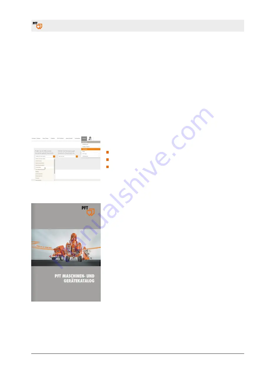
The spare parts lists for the machine can be found on the Internet at

www.pft.net.

Open the Document Centre under Service → Downloads.
In this area, select the spare parts list category.
In addition, select the machine you are looking for.

5.5.1

Accessories

Recommended accessories/equipment can be found in the PFT

machine and equipment catalogue or under www.pft.net

page 33 / 40

Summary of Contents for 20230100

Page 1: ...ting manual PFT levelling pin Safety overview operation and service Item no of the operating manual 00609892 Floor screed levelling pin Item no 20230100 Read the operating manual prior to starting any...

Page 2: ...on of this document exploitation or communication of its contents are prohibited unless expressly autho rised Violations may lead to damage compensation All rights are reserved in the event of patent...

Page 3: ...ging 17 3 Description 19 3 1 Overview of levelling pin 19 4 Operation 21 4 1 Safety 21 4 1 1 Monitoring the machine 21 4 2 Inspection by machine operator 22 4 3 Setting up the levelling pin 22 4 3 1 S...

Page 4: ...es of facts not necessarily to scale and may slightly differ from the actual model of the device 1 2 Information on the safety instructions These safety instructions give important information on hand...

Page 5: ...erted CAUTION Indicates a possibly dangerous situation which may lead to minor injuries if not averted NOTE Indicates a possibly dangerous situation which may lead to material damage if not averted Ti...

Page 6: ...nical changes Additionally the obligations defined in the delivery contract the general terms and conditions the delivery requirements of the manu facturer and the valid regulations at the time of con...

Page 7: ...al help and information Information on the respective contact partners can be found by tele phone fax e mail or on the Internet The address of the manufacturer can be found on the back page Our employ...

Page 8: ...device During the entire operation time of the device the owner is respon sible for coordinating the operating instructions with the current operational status and for adapting them as required The ow...

Page 9: ...al training knowledge and experience as well as knowledge of the relevant regulations in a position to carry out the work assigned to him and to recognise possible dangers inde pendently Qualified ele...

Page 10: ...ent Wear protective gear is necessary while working in order to minimise health risks Always wear the protective equipment required for the work in question during work Observe signs for personal prot...

Page 11: ...ear for special work Special protective equipment is necessary for certain specialist tasks It is separately mentioned in the individual chapters of this manual This special protective equipment is ex...

Page 12: ...power supply and secure to prevent switching on again Do not bypass fuses or disable them Observe the correct electrical amperage when replacing fuses Keep electrical parts away from sources of moistu...

Page 13: ...on when working Only remain in the danger zone for as long as absolutely necessary Hazardous dusts WARNING Health hazard caused by dust In the long term inhaled dust can lead to lung damage or have ot...

Page 14: ...uishers handy Familiarise personnel with accident reporting first aid and rescue equipment Keep access routes free for emergency vehicles When accidents happen Trigger emergency stop immediately Initi...

Page 15: ...pull cords etc 1 10 Intended use 1 10 1 Intended use of levelling pin The device has been designed and constructed only for the intended use described below The PFT levelling pin is used for levelling...

Page 16: ...n lead to dangerous situa tions Therefore Use the device only for the purpose specified Always adhere to the usage directives of the material manufacturer Strictly follow all instructions in this oper...

Page 17: ...s and trans port damage In case of externally visible transport damage proceed as follows Do not accept the delivery or under reserve only Note the extent of damage on the transport documentation or o...

Page 18: ...ls according to type and size and reuse or recycle NOTE Environmental damage due to incorrect disposal Packaging materials are valuable raw materials and in many cases they can be reused or reconditio...

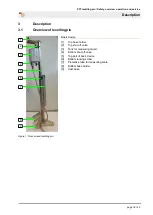
Page 19: ...elling pin 9 8 1 2 3 4 5 6 7 Figure 1 Floor screed levelling pin Basic device 1 Top hose holder 2 Top shut off valve 3 Tank for measuring liquid 4 Bottom shut off valve 5 Top part of basic device 6 Bo...

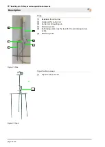
Page 20: ...Probe Probe 1 Extension for carrier rod 2 Guide part for carrier rod 3 Carrier rod for levelling pin 4 Measuring scale 5 Self closing valve only the lever for the self closing valve is visible 6 Measu...

Page 21: ...lead to serious damage to persons or property Therefore Carry out all operating steps according to the instruc tions in this user manual Prior to starting your work ensure that all components are comp...

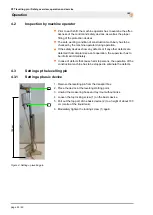
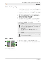
Page 22: ...a safe operation the supervisor has to be informed immediately In case of defects that cause harm to persons the operation of the construction machine has to be stopped to eliminate the defects 4 3 Se...

Page 23: ...e rod vertically close to the basic device on the floor level to be measured the liquid level will level off 6 Read off the liquid level the self closing valve 3 must still be open 7 Close the self cl...

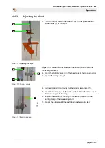
Page 24: ...of every measurement and must remain fixed during every measurement cycle Reference levels can be transferred easily and reliably by means of a marking square 2 that can be attached to the housing 1...

Page 25: ...ng valve on the probe 6 Set the liquid column to a round number preferably 0 100 by moving the top part of the basic device and make a note of this In this way ceiling soffits can be levelled in secon...

Page 26: ...in the base tank 7 After venting close the shut off valves 1 and the self closing valve 2 4 4 Setting up tripods 4 4 1 Tripod 1 2 3 Figure 9 Tripod The tripods are the auxiliary points that indicate t...

Page 27: ...asting surface and the measuring mandrel 2 Open the shut off valves 3 of the base tank at the top and bottom 3 Open self closing valve 4 5 100 cm Figure 12 Marking square 4 Set liquid column to a roun...

Page 28: ...the hose is not kinked or squeezed at any point NOTE Make sure the two shut off valves on the basic device are closed NOTE In certain probe positions it is not possible to exclude the measuring liqui...

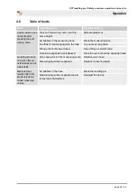
Page 29: ...or shut off valve Liquid column does not settle after pressing the self closing valve Hole in the expansion tank blocked Clear the rear hole on the expansion tank Valve hose stuck in the measuring sc...

Page 30: ...ng around or stacked on one another can cause accidents If components have been previously removed ensure that they are mounted again correctly reattach all fastening elements and adhere to the specif...

Page 31: ...Implementation by a service technician A service technician is responsible for the assembly and commissioning of machines In addition service techni cians carry out maintenance and repair work If wor...

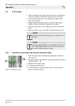
Page 32: ...Opening shut off valves 1 Open the shut off valves 1 and the self closing valve 2 2 Bring the shut off valves 1 and self closing valve 2 to the same level 3 4 5 Figure 17 Venting 3 Pull the measuring...

Page 33: ...ment used have been removed from the work area 4 Clean the work area and remove any spilled materials such as liquids processing material or similar 5 Ensure that all safety systems of the installatio...

Page 34: ...rior to starting the works ensure that there is suffi cient space Carefully handle components with sharp edges Ensure order and cleanliness at the working place Loose components and tools on top of on...

Page 35: ...rk safety and environmental protection regula tions Prior to starting the disassembly Switch off device and secure against restarting Disconnect the entire energy supply from the machine and discharge...

Page 36: ...of remaining components sorted according to the type of material NOTE Environmental damage due to incorrect disposal Electrical scrap and components lubricants and other process materials are subject...

Page 37: ...PFT levelling pin Safety overview operation and service Disposal page 37 40...

Page 38: ...PFT levelling pin Safety overview operation and service Disposal page 38 40...

Page 39: ...PFT levelling pin Safety overview operation and service Disposal page 39 40...

Page 40: ...S AT YOUR SITE Knauf PFT GmbH Co KG Postfach 60 97343 Iphofen Einersheimer Stra e 53 97346 Iphofen Germany Telephone 49 9323 31 760 Fax 49 9323 31 770 Technical hotline 49 9323 31 1818 info pft net ww...

Reviews: