Safety - Service Manual - Spare Part Lists
Settings Angularity on the Y- Arm
2011-04-07
11
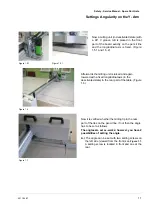
Figure 1.5.1
Figure 1.5.1
Now a milling unit (in deactivated state) with
a 90° V groove mill is placed in the front
part of the board exactly on the pencil line
and the longitudinal axis is fixed. (Figure:
1.5.1 and 1.5.2)
Figure 1.6
Afterwards the milling unit is raised and again
lowered with a fixed longitudinal axis (in the
deactivated state) in the rear part of the table. (Figure
1.6)
Figure 1.7
Now it is verified whether the milling tip in the rear
part of the lies on the pencil line, if not then the angle
has to be set as follows.
The angles are set ex-works; however, you have 2
possibilities of setting the angle.
A.)
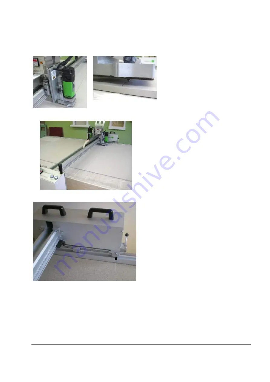
The angle can be set with two setting screws on
the left side (viewed from the front) see
Figure 1.7.
A setting screw is located in front and one at the
rear.

