Safety - Service Manual - Spare Part Lists
Settings Angularity on the Y- Arm
2011-04-07
13
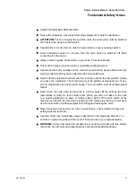
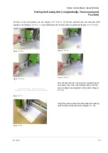
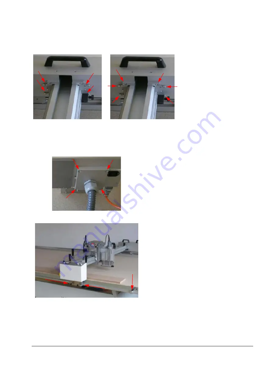
Figure 1.13
First, the lock nuts are opened
and the screws (
Figure 1.13
)
loosened, but not removed.
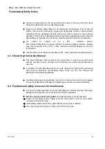
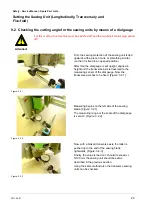
Figure 1.14
Afterwards the 4 screws on the
guide box and the 4 screws on
the terminal plate (
Figure 1.14
) are
loosened, but not removed.
B.)
Should the above mentioned
variants not be sufficient for
setting the angle, the one can
set the angle on the
equipment head as follows:
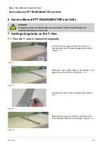
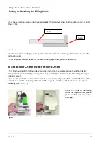
Figure 1.15
Afterwards, the 4 screws on the rear clamping plate
(
Figure 1.15
) are loosened, but not removed.
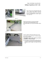
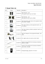
Figure 1.16
Only now can the Y-rail be shifted leftwards or
rightwards with a light pressure.
During this task, the front stop limits (
Figure 1.16
)
left, right on the Y-slide must be shifted, and the
screws fastened, so that the slide is fixed.
Afterwards, the rear side of the guide box is
shifted leftwards or rightwards until the angle is
correct and the screws initially loosened at this
point and tightened again in the reverse order.
It is recommendable to repeat the fine setting as in variant "A".

