background image


Safety - Service Manual - Spare Part Lists  


Safety Designation in this Manual 


2011-04-07


3  Safety Designation in this Manual 

The safety symbols together with the text of the safety note should draw attention to the unavoidable rest 
danger when operating the machine. This rest danger refers to persons, the machine, other things, and 
objects, the environment. 

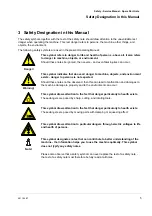
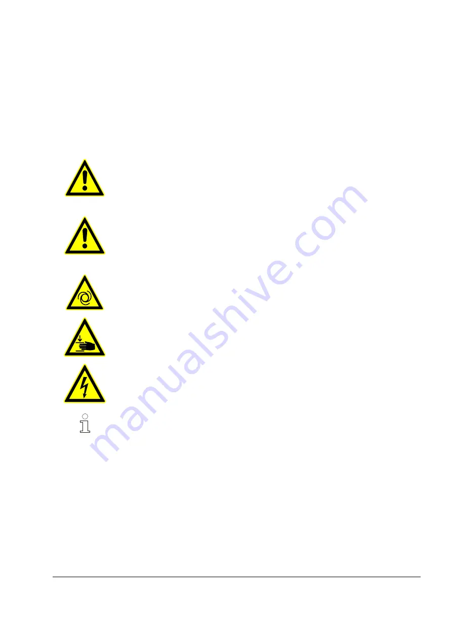
The following safety symbols are used in the present Operating Manual: 


Danger! 

This symbol refers to danger to life and health of persons - above all, it also refers 
to danger to machine, objects, or environment. 

Should these notes be ignored, then severe - and even fatal injuries can occur. 


Warning! 

This symbol indicates that above all danger to machine, objects, and environment 
exists - danger to persons is not expected. 

Should these notes not be observed, then this can lead to malfunction and damages to 
the machine damage to property and to the environment can occur. 


This symbol draws attention to the fact that danger particularly to health exists. 

These dangers are posed by sharp, cutting, and rotating tools. 


This symbol draws attention to the fact that danger particularly to health exists. 

These dangers are posed by moving parts with clamping or squeezing effect. 


This symbol draws attention to particular dangers through electric voltages to life 
and health of persons. 


Note! 

This symbol designates notes that can contribute to better understanding of the 
machine - the information helps you to use the machine optimally. This symbol 
does not typify any safety notes. 


Please also observe that a safety symbol can never replace the text of a safety note - 
the text of a safety note must therefore be fully read at all times. 


Summary of Contents for BOARDMASTER XL

Page 1: ...anual PFT BOARDMASTER XL Safety Service Manual Spare Part Lists Mobile table for cutting boards Article number of Operating Manual 00 23 71 34 Article number of the Machine 00 18 47 18 Read the Servic...

Page 2: ...PFT GmbH Co KG Postfach 60 97343 Iphofen Einersheimer Strasse 53 97346 Iphofen Germany Telephone 49 0 93 23 31 760 Telefax 49 0 0 93 23 31 770 Technical Hotline 49 9323 31 1818 info pft iphofen de In...

Page 3: ...ty measures for maintenance 8 5 Special Safety Notes for Operation 9 6 Service Manual PFT BOARDMASTER and Units 10 7 Settings Angularity on the Y Arm 10 7 1 First the Y arm is checked for angularity 1...

Page 4: ...ng over the equipment to third person hand over the Service Manual as well The diagrams in this Manual are not up to scale for the sake of representation of the subject matter and can slightly differ...

Page 5: ...ger to persons is not expected Should these notes not be observed then this can lead to malfunction and damages to the machine damage to property and to the environment can occur This symbol draws att...

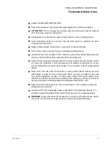
Page 6: ...trained personnel 4 2 General safety notes Use the machine appropriately The mobile cutting table for plates may only be used for the intended purpose Keep your machine and accessory in order A neglec...

Page 7: ...the rest position before you leave the workplace The mains plug must be pulled out whenever out of use prior to maintenance and during tool change The main switch must be locked against restart Never...

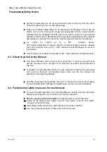
Page 8: ...eas explosion threatened areas 4 3 Observing the Service Manual This Service Manual must be kept by the service fitter It must be ensured that all persons that have to carry out tasks on the machine c...

Page 9: ...Special Safety Notes for Operation Warning of cut injuries Warning of hand injuries Protective goggles For the protection of eyes from flying parts and liquid sprays Ear protection For Protection aga...

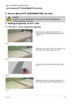
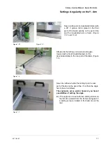
Page 10: ...ity on the Y Arm 7 1 First the Y arm is checked for angularity Figure 1 1 For this purpose a gypsum board is laid on the machine table which is placed against the rear rail Figure 1 1 Figure 1 2 After...

Page 11: ...milling unit is raised and again lowered with a fixed longitudinal axis in the deactivated state in the rear part of the table Figure 1 6 Figure 1 7 Now it is verified whether the milling tip in the...

Page 12: ...ust always be screwed in or out in opposite direction By displacing these screws the Y arm is swivelled either leftwards or rightwards via the pivot Figure 1 9 Figure 1 10 Figure 1 10 Figure 1 11 It s...

Page 13: ...equipment head as follows Figure 1 15 Afterwards the 4 screws on the rear clamping plate Figure 1 15 are loosened but not removed Figure 1 16 Only now can the Y rail be shifted leftwards or rightward...

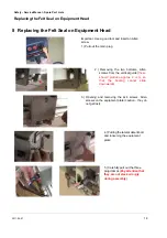
Page 14: ...2 Removing the two bottoms Allen screws from the vertical guide these should protrude approx 2 mm so that the bearing cannot slide downwards 3 Opening and removing the 4x4 screws Allen screws on the e...

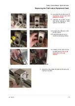
Page 15: ...ive residue 7 Cleaning the suction nozzle with brake cleaning or Nitro grease and dust free 8 Applying the adhesive on the suction nozzle 9 Putting the felt seal on the nozzle and pressing it firmly 1...

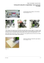
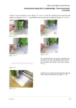
Page 16: ...n the screws tighten with care and tighten again 14 Tighten the two Allen screws of the guide rail 9 Setting the Sawing Unit Longitudinally Transversely and Five fold 9 1 Checking and setting the cutt...

Page 17: ...xis both brakes are fixed Figure 3 1 3 Switch on the swing unit and cut into the gypsum board once with the sawing unit The sawing unit should be lowered very slowly and for machines with hydraulic li...

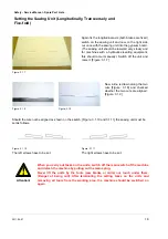
Page 18: ...ow a line is drawn along the two cuts Figure 3 1 8 and checked whether the two cuts are aligned Figure 3 1 9 Should the cuts not be aligned as shown on the sketch Figure 3 1 10 and 3 1 11 the sawing u...

Page 19: ...ch Figure 3 1 12 1 2 and afterwards the internal nuts are tightened Figure 3 1 12 3 4 Figure 3 1 12 1 Figure 3 1 12 2 Figure 3 1 12 3 Figure 3 1 12 4 Figure 3 1 13 Now the test with the cuts has to be...

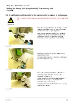
Page 20: ...this the dial gauge is set upright aligned in height and the transverse axis is traversed to the measuring sensor of the dial gauge Now the transverse axis has to be fixed Figure 3 2 1 Figure 3 2 2 M...

Page 21: ...he cutting angle of the cut board with an angle Figure 3 3 1 Figure 3 3 1 The bottom screws have to be set Figure 3 3 2 The bottom screws have to be set Should the cutting angle as shown on the upper...

Page 22: ...ng or Checking the Milling Units The milling housing of the milling units is manufactured and set ex works exactly in the right angle By improper fiddling with the milling unit e g dropping it can hap...

Page 23: ...ipment head set 4 pcs No 50168B 4 00 20 83 33 Idem spare bearing central equipment head 1 pcs No 50169A 5 00 20 83 34 Idem spare bearing eccentric equipment head 1 pcs No 50169B 5 00 20 83 35 Spare pa...

Page 24: ...Parts List 2011 04 07 24 55 00 20 83 42 MA Sensor for the digital display IVO No 071 40121 56 00 20 83 43 Magnetic tape longitudinal with protective plate No 071 40119 57 00 20 83 44 Magnetic tape tr...

Page 25: ...Safety Service Manual Spare Part Lists Notices 2011 04 07 25 12 Notices...

Page 26: ...Safety Service Manual Spare Part Lists Notices 2011 04 07 26...

Page 27: ...Safety Service Manual Spare Part Lists 2011 04 07 27...

Page 28: ...04 07 28 PFT THE FLOW OF PRODUCTIVITY Knauf PFT GmbH Co KG Postfach 60 97343 Iphofen Einersheimer Strasse 53 97346 Iphofen Germany Telephone 49 9323 31 760 Telefax 49 9323 31 770 Technical Hotline 49...

Reviews: