background image


Container Mixing Pump CMP 30 4.0 Part 2: Overview – Operation – Spare Part Lists 

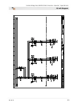
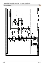
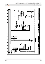
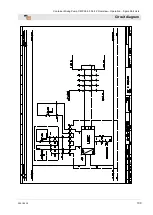
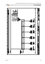
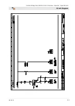
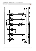
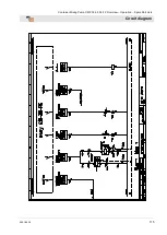
Circuit diagram 


2021-02-10


105 


Summary of Contents for CMP 30 4.0

Page 1: ...ing Manual Container Mixing Pump CMP 30 4 0 Part 2 Overview Operation Spare Part Lists Item number of operating manual 00686687 Item number of the machine parts list 00627857 Read the operating manual prior to beginning any work ...

Page 2: ...2 2021 02 10 Knauf PFT GmbH Co KG Postfach 60 97343 Iphofen Einersheimer Straße 53 97346 Iphofen Germany Tel 49 9323 31 760 Fax 49 9323 31 770 Technical hotline 49 9323 31 1818 info pft net www pft net ...

Page 3: ...y regulations 20 16 Transport packaging and storage 21 16 1 Safety instructions for transport 21 16 2 Transport checklist 22 16 3 Transport by car or truck 22 16 4 Transport 22 16 5 Transport safety 23 16 6 Transport with a forklift truck 23 16 7 Transportation of operational machines 24 17 Packaging 25 18 Safety 25 19 Set up silo with CMP 26 20 Safety device 26 20 1 EMERGENCY OFF pushbutton 26 20...

Page 4: ...ng mortar 43 36 1 Switching to automatic mode 44 36 2 Opening the air tap on the spray gun 45 36 3 Interruption of work 45 36 4 In the event of a work stoppage pause 46 36 5 Switching off the air compressor 46 37 Remote control 46 37 1 Using the remote control without spray gun 46 38 Measures to be taken in the event of a water supply failure 47 39 Switching off in an emergency 47 39 1 Emergency O...

Page 5: ...Frame CMP 30 4 0 Art No 00628863 76 51 6 Spare parts list for frame CMP 30 4 0 Art No 00628863 77 51 7 Dosing tube CMP 30 4 0 78 51 8 Spare parts list for dosing tube CMP 30 4 0 79 51 9 Bag insertion cover CMP 30 4 0 80 51 10 Bag insertion cover CMP 30 4 0 81 51 11 Gear motor with sealing unit CMP 30 4 0 cpl 82 51 12 Spare parts list gear motor with sealing unit CMP 30 4 0 cpl 83 51 13 Pump contai...

Page 6: ...Container Mixing Pump CMP 30 4 0 Part 2 Overview Operation Spare Part Lists Contents 6 2021 02 10 52 EC Declaration of Conformity 103 53 Circuit diagram 104 54 Index 116 ...

Page 7: ...e supervisor must be notified immediately For defects posing a hazard to persons the operation of the machine must be halted until the defect is eliminated 1 2 Periodic inspection Construction machines must be tested for safe operation by a specialist as the usage conditions and operating circumstances require but at least once a year Pressure vessels must undergo the prescribed inspections by aut...

Page 8: ...o operators at all times Always include the operating manual when transferring the machine to third parties The diagrams and illustrations shown in the manual are intended for better understanding of tasks and descriptions They are not necessarily shown to the correct scale and may vary slightly from the actual equipment used 2 2 Keep the manual for later use The operating manual must be available...

Page 9: ...ng Pump CMP 30 4 0 Part 2 Overview Operation Spare Part Lists Equipment or accessories 2021 02 10 9 3 Equipment or accessories You can find equipment or accessories for the machine in the Internet at www pft net 1 2 ...

Page 10: ...ree phase current 50 H 400 V Max current consumption 32 A Max power consumption 15 kW Connection 32 A Fuse At least 3 x 25 A Motor protection switch Fig 1 Motor protection switch Specification Service Setting value Designation Pump motor 7 5 kW 15 A Mixer motor 4 0 kW 8 3 A Q2 Water pump 1 1 kW 0 37 A Q4 Compressor 0 9 kW 1 8A Q6 Vibrator Q6 Water connection Specification Value Unit Operating pres...

Page 11: ...t Maximum continuous operating period 8 hours 4 4 Output values Pump output R7 3S Specification Value Unit Pumping capacity approx 7 26 l min Max operating pressure 30 bar Pumping distance max at 50 mm Ø 50 m Recommended value depending on conveying height condition and version of pump mortar quality composition and consistency 5 Sound power level Sound power level LWA 95 dB A 6 Vibrations Weighte...

Page 12: ...found in the control box and contains the following details Manufacturer Type Year built Machine number Permissible operating pressure 9 Quality control sticker Fig 4 Quality control sticker The quality control sticker contains the following information CE confirmed in compliance with EU directives Serial no serial number Controlled by signature Date of control 1940 940 1240 910 ...

Page 13: ...motor 3 Sack insertion 4 Filter hose rain protection 5 Transport lock for welding to the Sio 6 Silo connection 7 Water inlet into the mixing tube 8 Emergency OFF button 9 Rubber mixing pipe 10 Square outer bearing 11 Plaster piece for cleaning the mortar hoses 12 Connection of the mortar hoses to the pump unit 13 Mortar pressure gauge 14 Pump unit R7 3S 15 Control box 16 Pump container 17 Oil seal...

Page 14: ...2 Emergency OFF button 3 Water inlet into the mixing tube 4 Water connection from water fitting to mixing tube 5 Position switch for mixing tube 6 Capacitive level probe 7 Pump motor 8 Oil sealing unit 9 Pivot pin for transportation lock 10 Snap lock with catch 11 Position switch for pump unit 12 Connection of the mortar hoses to the pump unit 13 Water connection from mains or water barrel ...

Page 15: ...t door 5 Socket 230 V continuous current 6 Step switch operating modes 7 Water inlet button 8 Control lamp fault 9 Speed controller for pump motor 10 Pump OFF indicator light 11 Filter fan for switch cabinet 12 Connection remote control pump motor 13 Main power supply 14 Outlet filter for control box 15 Reserve 16 Vibrator connection 17 Mixer motor connection 18 Emergency OFF button 19 Indicator l...

Page 16: ...iew of pump motor with tank and pump 1 Pump motor 2 Oil sealing unit 3 Level probe KPS1 for pump container 4 Wheel for pump container 5 Safety switch for protective grids 6 Protective grille 7 Mortar pressure gauge 8 Connection for the mortar hoses 9 Pump unit R7 3S 10 Tie rod M16 11 Snap lock with catch 12 Pump shaft 13 Cleaning nozzle for draining residual material from the pump container ...

Page 17: ...box 175 rpm 4 Sealing unit 11 4 Pump container Fig 10 Pump container 1 Level probe KPS1 for pump container 2 Wheel for pump truck 3 Safety switch for protective grids 4 Cleaning nozzle for draining residual material from the pump container 11 5 Frame CMP30 Fig 11 Frame CMP30 1 Connection to silo or container 2 Position switch 3 Capacitive level probe 4 Pivot pin for transport security 5 Quick fast...

Page 18: ... air pump stops mixer continues to run 4 Air compressor 5 Water safety switch 6 Pressure reducer 7 Solenoid valve 8 Water flow meter 9 Needle valve for water quantity 10 Water tap cleaning hose 11 Water connection from water supply 12 Air connection to spray gun 13 Water connection for cleaning the mortar hose 14 Water pressure gauge 15 Water primary pressure gauge 16 Water pump 17 Drain valve Wat...

Page 19: ...tch position 2 the mixer motor runs Mixer and water pump run in manual mode The mixer is switched off by the level probe in the pump material container when the signal is full Fig 16 Step switch 3 Position 3 In switch position 3 the pump motor runs Pump runs in manual mode NOTE Never allow the pump to run dry Fig 17 Step switch 4 Position 4 Container mixing pump runs in automatic mode NOTE Water f...

Page 20: ...p the plant and also for cleaning at the end of work For a trouble free operation of the system an appropriate water pressure is necessary With the integrated water pump it is also possible to feed water from a reservoir water barrel if there is not enough water If the water pressure is too low the pressure switch built into the water supply automatically switches off the PFT CMP 30 4 0 to prevent...

Page 21: ...ediately before assembly Suspended loads WARNING Danger of death due to suspended loads Falling or swinging parts can pose a fatal hazard when heavy loads are lifted Therefore Never step underneath suspended loads Follow instructions regarding the provided suspension points Do not attach lifting tackle to protruding machine parts or to eyelets of add on components Ensure the lifting gear is fasten...

Page 22: ...ubmit a claim for the defects as soon as they are detected 16 3 Transport by car or truck DANGER Risk injury due to unsecured load All persons involved in the loading are responsible for securing the load properly during road transport The relevant vehicle driver is responsible for the operational loading Fig 20 Truck transport NOTE Truck transport Pay attention before each journey Close the switc...

Page 23: ...the chains none of the chains clamps or screws are damaged all chains are evenly tensioned 2 1 Fig 23 Transport safety Important Secure the pump unit before transport with the socket pin 1 and the quick coupling 2 Pay attention to the red colour markings on the frame The label must be clearly legible at all times Replace damaged or no longer legible stickers 16 6 Transport with a forklift truck Fi...

Page 24: ...y due to leaking mortar Injury to the face and eyes can occur Therefore Make sure all hoses are depressurised before opening the couplings note the indicator on the mortar pressure gauge 1 Carry out the following steps before transporting 2 First unplug the main power cable 3 Loosen all other cable connections and water hoses 4 Begin transport 5 Remove loose parts during crane transport ...

Page 25: ...packaging have been made separate the materials according to type and size and reuse or recycle them accordingly CAUTION Environmental damage can result from improper disposal of materials Packaging materials are valuable resources and can often be reused or recycled Therefore Dispose of packaging materials in an environmentally sound manner Observe locally applicable waste disposal guidelines If ...

Page 26: ...hearing loss Operation can result in noise that exceeds 95 dB A in close proximity to the machine Close proximity is defined as the area within 5 metres of the machine 19 Set up silo with CMP DANGER Risk of accident due to tipping silo Set up the silo or container with machine on a level and well secured surface It must be ensured that the subsoil does not give way due to the load on the silo and ...

Page 27: ...ed on the installation cabinet 2 WARNING Danger to life by disabling safety devices Never carry out illegal actions on safety equipment that endanger the life or health of employees 20 2 Position switch for pump unit Fig 27 Position switch If the pump unit is released while the machine is running the machine is switched off via the position switch 1 20 3 Position switch for mixing tube Fig 28 Posi...

Page 28: ...re gradient initial after pressure 1 bar Maximum media and ambient temperature 75 C Installation position unimportant preferably vertical 21 2 Purpose of solenoid valve Application range Solenoid valves for liquid and gaseous media aggressive or neutral can be used in various temperature and pressure ranges Type 6213 is a 2 2 way straight through solenoid valve closed without power with a positive...

Page 29: ... use 22 Intended use of air compressor 22 1 Purpose of air compressor The equipment has been designed and constructed only for the intended use described below Caution The air compressor is only intended for generating compressed air and may only be used with connected work devices Another use or a use extending beyond this such as with freely accessible and or open hoses or pipes is deemed to be ...

Page 30: ...mpressor corresponds to the national and international safety regulations and can therefore also be used in damp rooms or in the open air Areas with as clean and dry air as possible should be preferred Make sure that the device can suck in the air unimpeded This applies in particular when an installation is intended The air compressor must be set up so that no hazardous admixtures such as solvents...

Page 31: ...nk by the PFT water pump for the constant water supply to the PFT machine engineering The flow pressure of min 2 5 bar when the machine is running is ensured on size by drawing water from the water tank Connection example Fig 30 Water pump and water barrel Accessories Inlet strainer with stainless steel filter screen 1 suction hose 2 5 m item number 00136619 Water pump as suction pump AV 1000 stan...

Page 32: ... of water pump Fig 31 Filling the pump Before putting the PFT water pump into operation for the first time fill the pump with water so that the air in the pump housing is displaced Fill in water via the water inlet 1 In the water inlet 1 Check strainer Do not fill too quickly so that the air has time to completely escape from the housing It is advantageous if the suction hose is also filled with w...

Page 33: ...he water pump as close as possible to the water supply point pressing is better than sucking When all these points have been observed the pump can be switched on Depending on the length of the suction hose priming may take a few seconds If the pump is still not delivering after a short time this may have one of the following causes There is still air in the pump and this has to be completely vente...

Page 34: ... a single constructive unit together with the machine Failure to follow these recommendations will result not only in the voiding of the warranty but the quality of the mortar you are producing will also suffer 27 Mortar pressure gauge Important For reasons of safety the use of a mortar pressure gauge is recommended Fig 34 Mortar pressure gauge PFT mortar pressure gauge Benefits of the mortar pres...

Page 35: ... Connection to the 400 V power supply Fig 36 Power supply Connect the machine 1 to three phase current with 400 V DANGER Danger of death due to electric current The electrical connection must be fused correctly For the operation of frequency converters only connect the machine to a power source with an approved FI circuit breaker 30 mA RCD residual current device of type B that is sensitive to all...

Page 36: ...nection 1 Close water taps 1 2 Establish a connection to the water supply with a hose 3 Clean and bleed the water hose from the water mains and connect it to the water inlet 2 NOTE Only use clean water that is free of particulates The minimum pressure is 2 5 bar when the machine is running In order to vent the hose line and clean it from dirt the water supply line must first be flushed Observe the...

Page 37: ...allow the water pump to run dry since this will significantly shorten its service life 30 Switching on CMP 30 4 0 30 1 Setting the water volume Fig 42 Switching on 1 Turn the main switch 1 to the I position 2 Press the green operation ON pressure switch 2 3 Turn the step switch 3 to 0 4 To adjust the water quantity press the water flow button 4 Fig 43 Setting the water volume 5 At the same time ad...

Page 38: ...witching over the step switch NOTE In general before switching over the step switch 1 to other operating modes the control voltage should be switched off via the ON OFF operation pushbutton 2 Then switch on the control voltage again via the pushbutton 31 Mortar pressure gauge Fig 47 Mortar pressure gauge DANGER Operating pressure too high Machine components can fly open in an uncontrolled manner a...

Page 39: ...ust mask when filling the machine The decisions of the Committee for Hazardous Materials AGS can be read in the Technical Rules for Hazardous Substances TRGS 559 33 Switching on the horizontal mixer 33 1 Releasing the fuses for the pump unit 2 1 Fig 49 Releasing the pump unit 1 Pull out the hinge pin 1 and release the tension lock 2 Fig 50 Moving the pump container 2 Push the pump with pump contai...

Page 40: ...he mixer press the green pushbutton 5 Control voltage ON 7 Check mortar consistency 33 3 Switching off the mixer Fig 52 Switching off the mixer 1 Switch off the mixer press the red pushbutton 6 so the control voltage is OFF 33 4 Level probe in the mixer Fig 53 Fill level sensor 1 The material level in the material container of the horizontal mixer is monitored by the level probe 2 When the level s...

Page 41: ...lange and empty them completely of water 34 3 Draining residual water from the pump tank Fig 57 Opening the cleaning nozzles Fig 58 Connecting the mortar hose 1 Open the cleaning nozzle and drain off residual water from the pump container 2 Pre lubricate mortar hoses with approx 2 litres of wallpaper paste and connect them to the pressure flange again 3 The wallpaper paste is pumped through the mo...

Page 42: ...rial 2 has gone out 3 Turn the step switch 3 to 2 4 Switch on the horizontal mixer press the green pushbutton 4 control voltage ON 5 Fill the pump container with material 6 The mixer is automatically switched off by the level probe in the pump container NOTE Do not fill dry or too stiff material into the pump container This leads to hose blockages Never let the pump run dry 34 5 Level probe in the...

Page 43: ...n 2 to the mortar hose 4 35 3 Switching on the air compressor Fig 65 Air compressor 1 Switch on the air compressor at the rotary switch 1 2 As soon as the air compressor has built up pressure in the pipe system it switches off via the pressure cut off NOTE Check that the compressor is switched on by the black pressure switch on the motor protection switch 2 Compressor is only switched ON or OFF by...

Page 44: ...larity Wait until the consistency of the material has returned to normal NOTE The maximum pumping distance depends primarily on the flow characteristics of the mortar Heavy coarse grained mortar does not flow well Fluid materials have good flow characteristics If an operating pressure of 30 bar is exceeded thicker mortar hoses must be used 36 1 Switching to automatic mode Fig 66 Automatic mode 1 S...

Page 45: ...ial to be processed emerges NOTE The right mortar consistency is achieved if the material on the sprayed surface merges we recommend applying material to wall surfaces from top to bottom Uniform mixing and spraying cannot be ensured if the amount of water is insufficient This can clog the hoses and the pumping components are then subjected to greater wear 36 3 Interruption of work NOTE Generally t...

Page 46: ...ing off the air compressor 1 Switch off the air compressor at the rotary switch 1 2 Open air valve on the spray gun so that the residual pressure can escape DANGER Danger of injury due to leaking mortar Escaping mortar can lead to injuries to the eyes and face Beware of residual pressure 37 Remote control 37 1 Using the remote control without spray gun 1 Fig 72 Switching off the air compressor NOT...

Page 47: ... of a suction basket item number 00136619 and water pump Item Number 00492679 39 Switching off in an emergency 39 1 Emergency OFF button Fig 74 Emergency OFF button Machine movements and the energy supply must be disabled as quickly as possible in dangerous situations NOTE The Emergency OFF button is used to quickly put the machine into a safe state in case of danger or to avert a danger 39 2 Emer...

Page 48: ...ing properly 40 Measures to be taken in the event of a power failure 40 1 Turning the main switch to position 0 Fig 76 Turning the main switch to position 0 1 Close the air tap on spray gun 2 Turn the main switch to position 0 3 Switch off the air compressor at the rotary switch 4 Have the power supply connection checked by an expert 40 2 Discharging mortar pressure Fig 77 Mortar pressure at 0 bar...

Page 49: ...4 Switching on the machine again after a power failure 1 3 4 2 Fig 79 Restart lock NOTE The CMP 30 4 0 is equipped with a starting lock In the event of a power failure the system must be started as follows 1 Turn the step switch 1 to 0 2 Close the air tap on spray gun 3 Turn the main switch 2 to the I position 4 Switch on the air compressor at the rotary switch see Fig 80 5 Switch on the machine p...

Page 50: ...on either rectify it yourself or have authorised specialists do so NOTE A table below lists particular malfunctions and who is authorised to handle them 41 2 Fault displays The following equipment indicates a fault 1 2 3 Fig 81 Fault displays Pos LED signal Description 1 Control lamp yellow Lights up when no material is available 2 Control lamp yellow Lights up if there is not enough water pressur...

Page 51: ...ns Operator Service technician Gauge displays pressure below 2 2 bar Check water pump Service technician Machine does not start Power Power cable is defective Repair the power cable Service technician Main switch not activated Turn on the main switch Operator FI circuit breaker triggered Reset the FI circuit breaker Service technician Control lamp yellow fault Direction of rotation lights up Move ...

Page 52: ...e pump motor Service technician Defective connection cable Replace the connection cable Service technician Plug or mounted socket defective Replace plug or mounted socket Service technician Motor protection switch defective or actuated Replace or reset motor protection switch Service technician Material in pump container too dry Clean pump container Operator Machine stops after a short period Dirt...

Page 53: ... Replace mixing shaft Operator Driving claw defective Replacing the towing arm claw Service technician Control lamp red fault lights up Overload from the pump seizing up with dry material Allow the machine to run backwards otherwise remove pump and clean it Service technician Overload due to insufficient water quantity Increase water supply during start up Operator Motor protection switch of pump ...

Page 54: ...r hose to only briefly exceed 60 bar replacement of the mortar hose is recommended since unseen damage to the hose cannot be ruled out 42 Clearing hose blockages Fig 82 Checking the grout pressure DANGER Danger due to escaping material Never detach hose couplings if the feed pressure has not been fully released The conveyed material can escape under pressure and lead to serious injuries especially...

Page 55: ...e operator Only open the mortar hoses if the mortar pressure gauge 1 indicates the pressure has fallen to 0 bar DANGER Danger of injury due to leaking mortar Escaping mortar can lead to injuries to the eyes and face Always wear protective goggles Protective clothing protective gloves safety shoes ear protection Always position the machine so that you cannot be hit should mortar escape 1 Undo both ...

Page 56: ...n Chapter 37 1 43 End of work Cleaning the machine 43 1 Running the machine empty The machine must be cleaned daily after work 1 Close the silo discharge flap shortly before the end of work 2 The mixer continues to run until the dry material probe in the material container switches off the mixer 3 The pump continues to run until the level probe in the pump container switches it off 2 1 3 Fig 87 Cl...

Page 57: ...ixing tube cover CAUTION Water can enter sensitive machine parts Before cleaning the machine seal all openings where water could enter and impair the safety and functions of the machine e g electric motors and control boxes NOTE Do not aim the water jet at electrical components such as the gear motor or control box If the mixing tube is removed close the mixing tube adapter with the mixing tube co...

Page 58: ...un 4 Undo eye bolt 6 and pull air nozzle tube 7 out of the spray head 5 Open water outlet valve Pos 4 Fig 91 until the sponge ball emerges at the fine plaster device Repeat this procedure until the hose is cleaned 6 For different hose diameters the hoses should be cleaned separately with the appropriate sponge balls 7 Repeat this procedure if heavily soiled 8 Knock free air nozzle tube 7 with mand...

Page 59: ...ouple water hose 3 to the rubber mixing tube NOTE When installing the components make certain they are clean and dry Ensure that the metering and mixing shaft is correctly seated Always keep quick release fasteners and seals in a clean condition Lightly grease bearing journals and connection points of the mixing shaft 43 7 Cleaning the pump container Fig 95 Cleaning the pump container 1 Clean the ...

Page 60: ... from the pump 6 Switch off the machine at the red pushbutton 3 so the control voltage is OFF NOTE After the end of work the power and water supply lines must be disconnected from the machine 44 Pump replacement DANGER Danger of death due to unauthorised restarting When working on malfunctions there is a danger of unauthorised switching on of the electrical supply This puts those in the danger are...

Page 61: ... since longer storage may cause the rotor and stator to become inseparably joined 45 Switching off the CMP 30 4 0 1 2 Fig 99 Switching off 1 Switch off the machine press the red pushbutton 1 so the control voltage is OFF 2 Turn the main switch 2 to the position 0 46 Measures to be taken if there is a risk of frost CAUTION Damage due to frost Water that expands on freezing inside the component can ...

Page 62: ... pushbutton Operation ON is pressed the water pump approx 35 seconds and the drain valves approx 60 seconds are drained for the set time 5 Switch off the machine press the red pushbutton 5 so the control voltage is OFF 6 Switch off the machine turn the main switch 2 to the position 0 47 Maintenance 47 1 Safety Personnel Unless otherwise stated the maintenance work detailed here can be carried out ...

Page 63: ... electrical components can move uncontrollably and cause serious injury Therefore Before starting work switch off the electrical power supply and secure it against being switched back on again Interrupt the power supply by removing the connection cable Securing against restarting DANGER Danger of death due to unauthorised restarting When working on malfunctions there is a danger of unauthorised sw...

Page 64: ...e is limited to a few checks The most important maintenance task is thorough cleaning after use Interval Maintenance task To be performed by Monthly Clean Replace filter of the compressor Service technician Monthly Clean replace the plastic screen in the dirt trap Operator Monthly Clean replace the dirt trap screen in the pressure reducer Service technician Yearly Clean filter mat for filter fan s...

Page 65: ...emove the screws 3 from the filter cover 4 Remove the filter cover 4 NOTE The filter cover opening is at the bottom 5 Fig 107 Filter of the air compressor 3 Remove filter 5 4 Blow out the filter from the inside to the outside or tap it out 5 Replace the filter if dirt is severe 6 Insert the filter with the rigid side of the filter 1 facing inwards 47 7 Strainer screen in pressure reducer Implement...

Page 66: ...amide hose 3 back into the screw connection Screen for pressure reducer Item number 20156000 47 8 Safety valve air compressor Fig 110 Safety valve Check whether the safety valve on the air compressor opens at 4 0 bar against a completely closed air line 47 9 Checking the sealing unit Fig 111 Sealing unit Refill the sealing unit with standard gear grease Weekly check at the sight glass of the seali...

Page 67: ...r mat 3 and close filter fan 1 47 12 After performing maintenance 1 After maintenance has been completed carry out the following steps before switching on again 2 Check that all previously loosened screw connections have a tight fit 3 Check that all previously removed protective devices and covers have been properly reattached 4 Ensure that all tools materials and other equipment have been removed...

Page 68: ...essure switch Fig 116 Air compressor pressure switch Switch on air compressor Switching off the air compressor Compressor 2 5 bar 3 1 bar 1 Switch the air compressor on or off at the rotary switch 1 NOTE Close the ball valve 2 for continuous operation of the air compressor 48 2 Adjusting the level probe 1 3 2 Fig 117 Adjusting the level probe NOTE The level probe with adapter plate 1 can be indivi...

Page 69: ...an cause injuries Therefore Ensure there is adequate space before starting any work Exercise caution when working with open sharp edged components Keep the work area clean and tidy Components and tools that are stacked on one another or left lying around can cause accidents Disassemble components correctly Bear in mind that individual components can be heavy Use lifting equipment if necessary Secu...

Page 70: ...well as residual processing materials and dispose of them in an environmentally sound manner 50 Disposal Provided no return or disposal agreements have been made recycle the disassembled parts Metallic parts are scrapped Plastic elements are recycled Remaining components are disposed of sorted by individual material CAUTION Environmental damage can result from improper disposal of materials Electr...

Page 71: ...Container Mixing Pump CMP 30 4 0 Part 2 Overview Operation Spare Part Lists Disposal 2021 02 10 71 ...

Page 72: ...0 Part 2 Overview Operation Spare Part Lists Spare parts drawings spare parts list 72 2021 02 10 51 Spare parts drawings spare parts list 51 1 Motor flange swivelling Art No 00628865 1 2 3 4 5 6 19 18 17 16 15 7 8 9 10 11 3 12 13 14 ...

Page 73: ...on cable 1 10 m CEE 4x16A SW M4 6 1 20428700 CEE plug 4 x 16 A 7 h black 7 1 00046138 Reduction plastic M25 x 1 5 8 1 00041127 Skintop connection M 20 x 1 5 9 1 00463264 Gear motor ZF21 4 kW 280 rpm RAL9003 10 1 20545702 Sealing ring gearbox seal D 107x40x5 11 1 20102905 Protection tube for grasping claw 12 4 20207801 Hex screw M8 x 35 VPE 10 13 4 20207800 Hex screw M8 x 30 VPE 10 14 1 20545701 Dr...

Page 74: ...p CMP 30 4 0 Part 2 Overview Operation Spare Part Lists Spare parts drawings spare parts list 74 2021 02 10 51 3 Rubber mixing tube Art No 00628868 1 2 3 4 5 6 7 8 9 10 28 27 26 25 24 23 22 21 20 11 12 13 14 15 16 17 18 19 ...

Page 75: ...t M8 x 20 galvanised 11 1 20209314 Serrated washer A 8 4 galvanised VPE 10 12 2 20208900 Lock nut M12 galvanised pack of 10 13 1 00036967 Rubber skirt mortar outlet flange CMP 14 5 20207101 Hexagon head screw M6 x 16 galvanised VPE 10 15 5 20209308 Washer 6 4 x 20 x 1 5 galvanised 16 5 20209300 Washer A 6 4 galvanised 17 5 20206200 Lock nut M6 galvanised 18 1 00627444 Mixing tube CMP 4 0 RAL9003 1...

Page 76: ...mp CMP 30 4 0 Part 2 Overview Operation Spare Part Lists Spare parts drawings spare parts list 76 2021 02 10 51 5 Frame CMP 30 4 0 Art No 00628863 1 2 3 4 5 6 7 8 9 10 11 22 21 27 26 25 24 23 18 12 13 14 15 16 17 18 19 20 ...

Page 77: ...lf tapping screw 3 5 x 9 5 galvanised 11 1 20610301 Capacitive level probe N O contact 12 2 20206203 Lock nut M4 galvanised 13 2 20209301 Washer B 4 3 galvanised 14 2 20100801 Quick release fastener with safety device M14 15 2 20208522 Cotter bolt 8 H11 x 58 x 54 cpl 16 1 00626798 Position switch CMP 30 4 0 17 2 20206409 Cylindrical screw M4 x 30 galvanised 18 2 00054002 Seal for material hopper C...

Page 78: ...Container Mixing Pump CMP 30 4 0 Part 2 Overview Operation Spare Part Lists Spare parts drawings spare parts list 78 2021 02 10 51 7 Dosing tube CMP 30 4 0 1 2 3 4 5 6 7 14 13 12 11 9 18 17 16 15 8 9 10 ...

Page 79: ... CMP 4 0 6 1 20206200 Lock nut M6 galvanised 7 1 00627252 Mixing tube adapter CMP 4 0 RAL9003 8 1 00679955 Safety guard CMP 4 0 lateral right 9 8 20209313 Washer B 8 4 galvanised VPE 10 10 4 20207810 Hexagon head screw M8 x 25 galvanised VPE 10 11 4 20207200 Lock nut M8 galvanised pack of 10 12 1 20549510 Rubber seal with fabric 13 1 20549514 Clamping flange for mixing tube seal HM 3 14 4 20209611...

Page 80: ...iner Mixing Pump CMP 30 4 0 Part 2 Overview Operation Spare Part Lists Spare parts drawings spare parts list 80 2021 02 10 51 9 Bag insertion cover CMP 30 4 0 14 8 13 12 11 10 17 16 8 14 15 1 2 3 4 5 6 7 8 9 ...

Page 81: ...h screw 6 1 00463874 Filter bag holder transfer hood RAL9003 7 4 20206100 Hex screw M 8 x 20 galvanised 8 6 20207200 Lock nut M8 galvanised 9 1 00133555 Seal for filter bag holder 2 mm 10 2 20206200 Lock nut M6 galvanised 11 2 20209300 Washer A 6 4 galvanised 12 2 00047820 Quick release fastener with safety device M10 13 2 20207104 Hexagon head screw M6 x 45 galvanised 14 2 20208701 Hex screw M 8 ...

Page 82: ...mp CMP 30 4 0 Part 2 Overview Operation Spare Part Lists Spare parts drawings spare parts list 82 2021 02 10 51 11 Gear motor with sealing unit CMP 30 4 0 cpl 1 2 19 18 17 16 15 14 13 12 11 24 23 22 21 20 3 4 5 6 7 8 9 10 ...

Page 83: ...W 175 rpm 8 4 00023284 Cylindrical screw with hex socket M10 x 25 galvanised 9 4 20209111 Spring washer B 10 galvanised 10 1 20144028 Oil sealing unit D 30 x 60 galvanised 11 1 20207501 Hex screw M10 x 30 galvanised 12 1 20102602 Seal USIT 16 x 10 x 1 5 13 1 20144077 Gasket D 53 5 x 10 5 T 10 14 1 20144015 O ring 50 x 2 15 1 20172113 Hub D 30 mm 16 1 20144021 Mechanical seal set oil sealing unit 1...

Page 84: ...peration Spare Part Lists Spare parts drawings spare parts list 84 2021 02 10 51 13 Pump container with pump shaft CMP 30 4 0 cpl Item Number 00628859 1 2 3 4 5 6 7 8 9 10 26 25 24 23 22 37 36 35 34 33 32 31 30 29 28 27 11 12 13 14 15 16 17 18 19 20 21 ...

Page 85: ... 4 0 16 2 20206409 Cylindrical screw M4 x 30 galvanised 17 2 20206203 Lock nut M4 galvanised 18 1 00002442 Hedgehog pump shaft 4 row CMP torsional damper cpl 19 1 00054031 Pluggable coupling hub for torsional damper RAL2004 20 1 00002064 Joint disc for pump shaft torsional damper 21 3 20208900 Lock nut M12 galvanised 22 1 00002443 Hedgehog pump shaft 4 row CMP for torsional damper RAL2004 23 3 202...

Page 86: ...xing Pump CMP 30 4 0 Part 2 Overview Operation Spare Part Lists Spare parts drawings spare parts list 86 2021 02 10 51 15 Pump unit CMP 30 4 0 Item Number 00628862 1 2 12 11 20 19 18 17 16 15 14 13 3 4 5 6 7 8 9 10 ...

Page 87: ...0044154 Pressure flange for R pump 11 4 AG RAL2004 7 1 20118910 Tie rod M16 x 630 mm set 8 2 20209921 Flanged nut M16 galvanised 9 2 20025035 Seal USIT U A 22x16x1 5 10 2 20118912 Tensioning screw M16 x 630 galvanised 11 2 20100801 Quick release fastener with safety device M14 12 2 20208522 Split pin bolt with washer and split pin galvanised 13 1 00626081 Pump flange CMP 30 4 0_2 18 RAL2004 14 1 2...

Page 88: ...Container Mixing Pump CMP 30 4 0 Part 2 Overview Operation Spare Part Lists Spare parts drawings spare parts list 88 2021 02 10 51 17 Control box CMP 30 4 0 VA 1 2 3 4 5 6 7 8 9 10 15 16 11 12 13 14 ...

Page 89: ...g cap nut M8 galvanised 5 1 00626148 Control box cover CMP 30 4 0 RAL9003 6 1 00058728 Clamping plate for compressor CMP 30 4 0 RAL2004 7 1 00058726 Distance plate for compressor CMP 30 4 0 RAL2004 8 2 20206100 Hex screw M 8 x 20 galvanised 9 1 00058266 Base plate for compressor CMP 30 4 0 RAL2004 10 3 20207200 Lock nut M8 galvanised 11 1 00053787 Mounting bracket for compressor control box CMP 30...

Page 90: ...p CMP 30 4 0 Part 2 Overview Operation Spare Part Lists Spare parts drawings spare parts list 90 2021 02 10 51 19 Air fitting CMP 30 4 0 1 2 3 4 5 6 7 8 23 22 2 21 20 19 27 2 24 17 6 26 25 24 2 9 10 11 12 13 14 15 16 17 18 ...

Page 91: ... High pressure valve 1 4 3 5 bar with sealing ring 11 4 20206400 Hex nut M8 galvanised 12 4 00059495 Rubber diaphragm D40 x 30 13 2 00058730 Guide rail for compressor CMP30 II RAL2004 14 4 00047103 Toothed lock washer A 8 4 15 4 20208701 Hex screw M 8 x 16 galvanised 16 1 20447600 Pressure switch type MDR F 0 22 4b 17 2 20203712 Screwed joint 1 4 male thread brass 18 1 20203651 Elbow 1 4 female th...

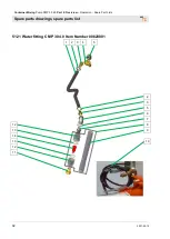
Page 92: ...ixing Pump CMP 30 4 0 Part 2 Overview Operation Spare Part Lists Spare parts drawings spare parts list 92 2021 02 10 51 21 Water fitting CMP 30 4 0 Item Number 00628081 1 2 3 4 5 12 13 14 13 12 11 2 3 5 6 7 8 9 10 ...

Page 93: ... 2 male thread 1 2 socket 4 1 20200900 Geka coupling 1 2 male thread pack of 10 5 2 20203611 Elbow 1 2 female thread galvanised 6 1 00023373 Washer B 23 galvanised 7 1 00023630 Double nipple hexagonal 1 2 galvanised 8 1 20185004 Water flowmeter 150 1 500 l h 9 1 00075955 Plastic tube 75 750 l h 150 1 500 l h 10 1 20213001 Water air hose Geka spray nozzle 3 m 11 1 20203105 Nipple with 1 2 male thre...

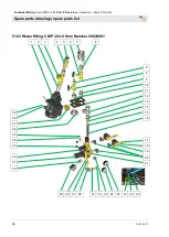
Page 94: ...eration Spare Part Lists Spare parts drawings spare parts list 94 2021 02 10 51 23 Water fitting CMP 30 4 0 Item Number 00628081 1 2 3 4 5 6 7 8 29 28 27 26 14 15 25 24 23 19 20 22 39 38 37 36 35 34 33 32 31 30 9 6 8 10 11 12 13 14 15 16 17 18 19 20 21 ...

Page 95: ...615 Water air hose 1 2 x 230 mm 17 2 20190411 Hose screw connection 1 4 male thread 1 2 socket 18 2 20209000 Washer B 13 galvanised VPE 10 19 2 00630996 Solenoid valve 1 4 42V type 6013A 7 Watt 20 2 00065902 L screw plug connection QSL G 1 4 12 21 1 00039286 Manifold block brass DK06FN 1 2 E 42V 22 1 00055198 Polyamide hose 8 x 6 x 1 PA11 12 running metre 23 1 00009367 Gauge 0 4 bar 1 4 rear D 50 ...

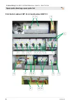
Page 96: ...mp CMP 30 4 0 Part 2 Overview Operation Spare Part Lists Spare parts drawings spare parts list 96 2021 02 10 51 24 Switch cabinet CMP 30 4 0 Item Number 00627311 1 2 3 18 17 16 15 14 13 12 21 20 19 4 11 8 10 7 9 7 8 7 6 5 ...

Page 97: ...9 Motor protection switch 0 63 1 A PKZM 0 1 9 1 00043842 Motor safety switch 6 10 A PKZM0 10 10 1 00042600 Motor protection switch 1 1 6 A PKZM 0 1 6 11 1 00042602 Motor protection switch 10 16 A PKZM 0 16 12 1 20452751 Phase sequence relay 200 500 V type FPF2 13 1 00084225 Air break contactor DIL M17 10 42 V 14 1 20446610 Air break contactor DIL EM 10 42 V 50 Hz 15 1 00462339 Switch mode power su...

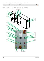
Page 98: ...4 0 Part 2 Overview Operation Spare Part Lists Spare parts drawings spare parts list 98 2021 02 10 51 26 Switch cabinet CMP 30 4 0 Item Number 00627311 1 2 3 4 12 14 13 12 5 6 7 8 9 10 11 24 23 22 21 20 19 8 18 10 17 8 16 10 15 12 ...

Page 99: ...0 Hz 8 3 00053839 Pushbutton without sensor plate M22 9 1 00053842 Sensor plate black liquid M22 10 3 00053830 Membrane round for pushbutton IP 67 11 1 00053875 Indicator lamp attachment red 12 3 00053874 Indicator lamp attachment yellow 13 1 00186375 Emergency OFF sign in four languages 14 1 00413582 Emergency OFF Emergency Stop button M22 15 1 00050783 Potentiometer 16 1 00053840 Touch plate gre...

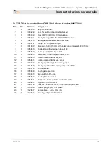
Page 100: ...Pump CMP 30 4 0 Part 2 Overview Operation Spare Part Lists Spare parts drawings spare parts list 100 2021 02 10 51 28 Switch cabinet CMP 30 4 0 Item Number 00627311 1 2 3 4 2 2 5 5 11 8 5 7 8 10 9 5 7 8 6 2 5 5 7 8 2 5 ...

Page 101: ...ltage release 400 V 50 Hz 2 5 00053835 Contact element 1 closer M22 K10 3 1 00462324 Indicating lamp LED 24 V DC multicoloured 4 3 00053836 Contact element 1 opener M22 K01 5 9 00053834 Fastening adapter for switch elements 6 1 00186372 Step switch 0 6 1 pole 7 3 00053881 Light element white 12 30 V 8 4 00053886 LED resistor series element for 42 V 9 1 00628484 Contact element 3 opener front 10 1 ...

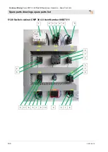
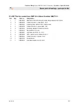
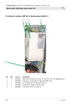
Page 102: ... Item Number 00627311 1 2 3 4 Pos Qty Item no Designation 1 1 00526273 EMC filter for frequency converter 7 5 kW 400 V 16 A low leakage current 2 1 00473802 Frequency converter 400 V Programmed CMP 30 4 0 3 1 00036323 Outlet filter for switch cabinet 150x150 mm 4 1 20427200 Safety panel mounted socket 16 A blue 5 1 00289880 Filter fan 24 V AC for control box 5 ...

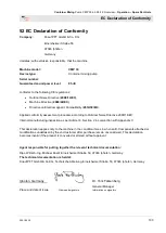
Page 103: ...Outdoor Noise Directive 2000 14 EC Internal manufacturing inspection as per Article 14 Section 2 in conjunction with Appendix V This declaration applies only to the machine in the condition it was in when sold Components attached or modifications undertaken by the end customer after purchase remain unconsidered This declaration becomes invalid if the product is converted or altered without approva...

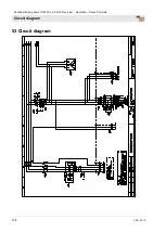
Page 104: ...Container Mixing Pump CMP 30 4 0 Part 2 Overview Operation Spare Part Lists Circuit diagram 104 2021 02 10 53 Circuit diagram ...

Page 105: ...Container Mixing Pump CMP 30 4 0 Part 2 Overview Operation Spare Part Lists Circuit diagram 2021 02 10 105 ...

Page 106: ...Container Mixing Pump CMP 30 4 0 Part 2 Overview Operation Spare Part Lists Circuit diagram 106 2021 02 10 ...

Page 107: ...Container Mixing Pump CMP 30 4 0 Part 2 Overview Operation Spare Part Lists Circuit diagram 2021 02 10 107 ...

Page 108: ...Container Mixing Pump CMP 30 4 0 Part 2 Overview Operation Spare Part Lists Circuit diagram 108 2021 02 10 ...

Page 109: ...Container Mixing Pump CMP 30 4 0 Part 2 Overview Operation Spare Part Lists Circuit diagram 2021 02 10 109 ...

Page 110: ...Container Mixing Pump CMP 30 4 0 Part 2 Overview Operation Spare Part Lists Circuit diagram 110 2021 02 10 ...

Page 111: ...Container Mixing Pump CMP 30 4 0 Part 2 Overview Operation Spare Part Lists Circuit diagram 2021 02 10 111 ...

Page 112: ...Container Mixing Pump CMP 30 4 0 Part 2 Overview Operation Spare Part Lists Circuit diagram 112 2021 02 10 ...

Page 113: ...Container Mixing Pump CMP 30 4 0 Part 2 Overview Operation Spare Part Lists Circuit diagram 2021 02 10 113 ...

Page 114: ...Container Mixing Pump CMP 30 4 0 Part 2 Overview Operation Spare Part Lists Circuit diagram 114 2021 02 10 ...

Page 115: ...Container Mixing Pump CMP 30 4 0 Part 2 Overview Operation Spare Part Lists Circuit diagram 2021 02 10 115 ...

Page 116: ...oupling the water hose to the mixing tube 38 Danger of frost 61 Dealing with malfunctions 50 Description of assemblies 15 Description of the PFT water pump accessories 31 Dimensions 12 Disassembly 70 Disassembly 69 Discharging mortar pressure 48 49 Disconnect mortar hose 57 Disposal 70 Dosing tube CMP 30 4 0 78 Draining residual water from the pump tank 41 Draining the water fitting 62 EC Declarat...

Page 117: ...oning 51 Disassembly 69 Installation 51 Position switch for mixing tube 27 Position switch for pump unit 27 Possible causes 54 Pre existing damage on mortar hose 54 Preparation 35 Preparation AV3 32 Preparing the mortar hoses 41 Proper use of the machine 31 Protective equipment Installation 51 Protective equipment for operators 25 Pulling the pump unit out of the frame 40 Pump container 17 Pump co...

Page 118: ... CMP 30 4 0 cpl 83 Stopper will not come loose 55 Storage 21 Strainer screen in pressure reducer 65 Switch cabinet CMP 30 4 0 Item Number 00627311 96 98 100 102 Switching off in an emergency 47 Switching off the air compressor 46 Switching off the CMP 30 4 0 61 Switching off the machine 38 Switching off the mixer 40 Switching on CMP 30 4 0 37 Switching on the air compressor 43 Switching on the hor...

Page 119: ...Container Mixing Pump CMP 30 4 0 Part 2 Overview Operation Spare Part Lists 2021 02 10 119 ...

Page 120: ...eration Spare Part Lists 120 2021 02 10 PFT ALWAYS AT YOUR SITE Knauf PFT GmbH Co KG Postfach 60 97343 Iphofen Einersheimer Straße 53 97346 Iphofen Germany Tel 49 9323 31 760 Fax 49 9323 31 770 Technical hotline 49 9323 31 1818 info pft net www pft net ...

Reviews: