Container Mixing
Pump CMP 30 4.0
Part 2: Overview –
Operation – Spare Part Lists
Description of assemblies
2021-02-10
15
11 Description of assemblies
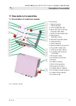
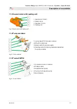
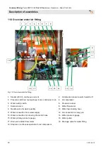
11.1 Description of control box module
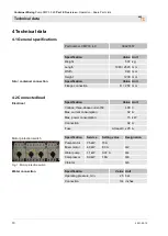
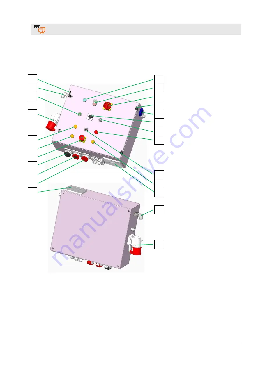
Fig. 7: Control box module
Control box
1. Relieve the pump
(reverse running).
2. Control voltage ON / OFF
3. Main switch, also functions as
Emergency OFF switch.
4. Hinges for switch cabinet door.
5. Socket (230 V),
continuous current.
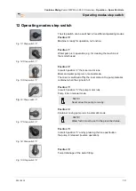
6. Step switch, operating modes.
7. Water inlet button.
8. Control lamp fault.
9. Speed controller for pump motor
.
10. Pump OFF indicator light.
11. Filter fan for switch cabinet.
12. Connection remote control
pump motor.
13. Main power supply.
14. Outlet filter for control box.
15. Reserve.
16. Vibrator connection.
17. Mixer motor connection.
18. Emergency OFF button
19. Indicator lamp (no material)
20. Control lamp no water pressure.
21. Vibrator manual operation.
22. Control box lock.
1
2
3
4
5
6
7
8
9
10
11
12
13
22
12
21
13
20
19
18
17
16
15
14


