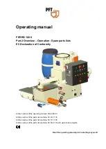
FERRO 100 II Part 2 Overview – Operation - Spare parts lists
Description of assemblies
14
2018-03-26
13 Description of assemblies
13.1
Assembly unit description control box
1
2
3
4
5
6
7
8
15 14 13 12 11 10 9
25
24
23 22
16 17 18 19
21 20
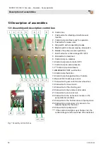
Fig. 7: Assembly unit control box
Control box
1. Push button for vibrating unit with manual
function.
2. Control lamp machine ready for operation.
3. Pushbutton for water inlet.
4. Step switch with six operating modes.
5. Master switch is also emergency-stop switch.
6. Release the pump (reverse operation).
7. Push button for control voltage ON / OFF.
8. Pushbutton for lamp test.
9. Control lamp no material.
10. Control lamp remote control OFF.
11. Control lamp no water pressure.
12. ***Control lamp motor failure.
13. EMERGENCY OFF push button.
14. Control lamp thermistor.
15. Control lamp change direction of rotation.
16. Socket 230V continuous current.
17. Connection to gear motor for star wheel lock.
18. Connection for mixer motor.
19. Connection for the vibrating unit.
20. Connection to the remote control cable.
21. Connection to main terminal.
22. Connection to the wet sensor / sensor in the
pump material container.
23. Connection to the thermal sensor of pump motor
24. Connection to dry sensor / dry sensor in the
material hopper for the mixer.
25. Connection for pump motor.
**** If the control lamp lights up or flashes red, the
control voltage must be switched off or restarted.

