FERRO 100 II Part 2 Overview – Operation - Spare parts lists
Work on troubleshooting
2018-03-26
35
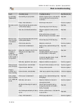
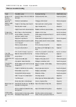
26.2 Fault displays
The following installation indicates faults:
Fault displays
2 3 4
1 5 6
Fig. 52: Fault displays
Pos. Light signal
Description
1
Control lamp red
Lights up when the motor
protection switch has been
triggered.
Check motor protection switch Q1 –
1
Control lamp blinks
red
If the limit switch is faulty or if the
mixing tube has been removed.
2
Control lamp yellow Control lamp change direction of
3
Control lamp yellow Control lamp thermistor
4
Control lamp yellow Control lamp no water pressure
5
Control lamp yellow Control lamp remote control OFF
6
Control lamp yellow Control lamp no material
NOTE!
Phase control lamp (7) green (ready for operation):
If there is a phase error in the power supply, this
lamp will not light and the machine will not be
switched on.
26.3
Faults
The following chapter describes possible causes for faults and the
activities carried out for their rectification.
In case faults occur frequently, shorten the maintenance intervals
in accordance with the actual load.
In the event of faults that cannot be rectified by means of the
following notes, kindly contact the dealer.
26.4
Safety
Personnel
The work for rectification of faults described here can be carried
out by the operator, unless marked otherwise.
Some works must be carried out only by specially trained skilled
personnel or exclusively by the manufacturer. Information on
this can be found in the description of the individual faults.
Work on the electrical system must, in principle, be carried out
only by electricians.
Personal protective equipment
The following protective equipment has to be worn for all
maintenance work:
Protective clothing
Protective goggles
Protective gloves

