background image


FERRO 100 II Part 2 Overview – Operation - Spare parts lists 


Spare parts drawing, spare parts list


72 


2018-03-26


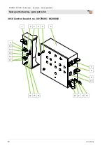
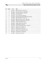
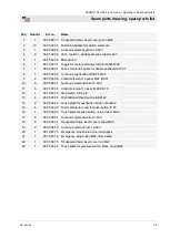
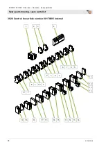
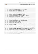
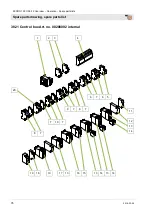
38.19  Control box Art. no. 00178685 / 00208092 


9  10  4  11 


21  20  2  19  11  4 


19  4 


11 

13 
11 

13 
14 


15 
23 
17 

18 

18 

17 

22 


12 

11 
13 


11 

14 
15 
16 
15 
17 

17 


18 

18 

17 

18 


Summary of Contents for FERRO 100 II

Page 1: ...aration of Conformity Article number of the operating manual 00 62 68 00 Article number of the parts list machine 00 23 21 39 Article number of the parts list machine 00 17 17 05 Article number of the...

Page 2: ...018 03 26 Knauf PFT GmbH Co KG P O Box no 60 97343 Iphofen Einersheimer Stra e 53 97346 Iphofen Germany Phone 49 9323 31 760 Fax 49 9323 31 770 Technical hotline 49 9323 31 1818 info pft net www pft n...

Page 3: ...00186555 16 13 4 Water supply heated Art no 00232147 17 14 Operating modes of selector switch 18 15 Functional description work flow 20 15 1 Basic equipment 20 15 2 Safety rules 20 16 Transport packi...

Page 4: ...3 1 Do not load the pump unit 48 34 4 Replace the pump motor 48 34 5 Do not load pump motor 48 34 6 Lubrication during maintenance 49 34 7 Cleaning filters 49 34 8 Environmental protection 50 34 9 Act...

Page 5: ...ble of Contents 2018 03 26 5 38 22 Control box Art no 00208092 internal 77 38 23 Star wheel lock FERRO II complete RAL1015 Article number 00035135 78 38 24 Water tank cmpl for FERRO II Trans RAL1015Ar...

Page 6: ...14 EC Internal production control as per article 14 paragraph 2 in connection with annex V This declaration only refers to the machine in the state in which it has been placed on the market Parts sub...

Page 7: ...the operation of the construction machine has to be stopped to eliminate the defects 3 Periodic inspection Construction machinery has to be inspected for their safe working condition in accordance wi...

Page 8: ...ible to the personnel at all times If the tool is given to third parties also include the operating manual The figures in this manual are for presentation purposes of facts not necessarily to scale an...

Page 9: ...t 15 kW CEE connection 5 x 32 A Fuse protection At least 3 x 25 A Connection cable min 5 x 6 mm Motor protection switch Figure 1 Motor protection switch Detail Power Setting Designation Pump motor 7 5...

Page 10: ...Operating pressure max 25 bar Feed range max at 50mm 100 m reference value depending on conveying height pump condition and version mortar quality composition and consistency 7 Sound power level Guara...

Page 11: ...t 2018 03 26 11 10 Dimension sheet Fig 3 Dimension sheet 11 Name plate Fig 4 Name plate The type plate is located in the control box and includes the following information Manufacturer Type Year of ma...

Page 12: ...r tank 5 Gear motor for star wheel lock 6 Filter bag ventilation 7 Swivel mounted motor flange 8 Gear motor for mixer 9 Connection to main terminal 10 Tool cabinet 11 Control box 12 Water installation...

Page 13: ...article number 00171705 6 7 8 Fig 6 Table of the assembly groups 1 Material hopper for mixer 2 Cleaning hole inspection window for wet sensor 3 Wet sensor for pump container 4 Pump material container...

Page 14: ...lamp test 9 Control lamp no material 10 Control lamp remote control OFF 11 Control lamp no water pressure 12 Control lamp motor failure 13 EMERGENCY OFF push button 14 Control lamp thermistor 15 Cont...

Page 15: ...ressure reducer 2 Manometer for hydraulic pressure of the booster pump 3 Power connection of the booster pump 4 Water from booster pump to the pressure reducer water flow meter 5 Distributor of power...

Page 16: ...ig 9 Water supply assembly 1 Power connection of the booster pump 2 Pressure switch 3 Water hose from booster pump to the distributor of water extraction hose cleaning 4 Water hose from network or wat...

Page 17: ...er chamber for pressure reducer 2 Pressure reducer 3 Pressure switch 4 Booster pump 5 Distributor of power connection of solenoid valves 6 Heater for water manifold 7 Power connection of the booster p...

Page 18: ...starts to fill the star wheel lock The control lamps are checked by pressing the lamp test button Fig 12 Selector switch water pump Main switch ON control voltage ON Selector switch water pump Manual...

Page 19: ...or container NOTE Never let the pump run dry Fig 16 Selector switch automatic Main switch ON control voltage ON Selector switch automatic mode 1 Machine runs in automatic mode 2 Star wheel lock fills...

Page 20: ...ystem and even the cleaning after finishing the work all functions can also be controlled manually at the control box For a more secure functioning of the system an appropriate water pressure is neces...

Page 21: ...WARNING Danger to life from suspended loads When lifting heavy loads there is danger to life from falling parts or uncontrolled swinging parts Therefore Never step under suspended loads Observe the in...

Page 22: ...lid warranty period Anchor points Fig 18 Crane transport Anchor the machine at the anchor points for transport by crane Observe the following conditions The crane and lifting equipment have to be desi...

Page 23: ...loading 16 5Transport Fig 19 Truck transport NOTE Truck transport Ensure the following before every ride That the chains between machine and silo are stretched and not damaged Lock control box door Co...

Page 24: ...tar Injuries to face and eyes can occur Therefore Before opening the couplings ensure that there is no more pressure on the hoses observe display at mortar manometer 1 Carry out the following steps be...

Page 25: ...made separate materials according to type and size and reuse or recycle ATTENTION Environmental damage due to wrong disposal Packaging materials are valuable raw materials and in many cases they can...

Page 26: ...encies At close range of the machine 95 dB A can be exceeded due to operational conditions Close range is a distance of less than 5 metres to the machine 19 Set up silo with Ferro Fig 21 Set up silo D...

Page 27: ...ibution box and the control box of the machine DANGER Danger to life from electric current The connection line has to be fused properly Connect the machine only to a power source with permissible RCCB...

Page 28: ...supply Fig 28 Water connection Connect to water supply with 3 4 hose The water supply line must first be rinsed to vent the hose line and to clean it of contaminations Connect the water hose to the w...

Page 29: ...e 4 to the left or right in a pre setting In this way the direction of rotation is selected If the switch is to the left it can be switched back to zero but is blocked for the right position Press the...

Page 30: ...ar manometer Fig 38 Mortar manometer DANGER Operating pressure too high Machine parts can open in an uncontrolled manner and injure the operator Therefore Do not operate the machine without mortar pre...

Page 31: ...nsure clean and correct connection of the couplings NOTE The possible conveying distance depends mainly on the flowability of the mortar Heavy sharp grained mortar has poor flow characteristics Runny...

Page 32: ...mode Selector switch 1 to position 5 automatic mode The control of the system runs in automatic operation in this switch position Automatic mode Star wheel lock starts while the vibrating unit simulta...

Page 33: ...amount of water on the diaphragm valve 3 can be corrected if necessary The amount of water is evident on the floater 4 of water flow meter 23 4Lamp test Fig 49 Lamp test NOTE Please press the push bu...

Page 34: ...ities 8 Assign specialised personnel with the troubleshooting WARNING Danger to life from premature reactivation On reactivation there is danger to life for all persons in the danger zone Before react...

Page 35: ...n the power supply this lamp will not light and the machine will not be switched on 26 3Faults The following chapter describes possible causes for faults and the activities carried out for their recti...

Page 36: ...le switching on Bring the selector switch in the middle position and switch on the control again Operator Control lamp Change direction of rotation lights up or is always lit up Change the direction o...

Page 37: ...ugh pump hopper is not yet filled Safety time stored in the PLC for filling the pump hopper has expired Briefly position the manual automatic switch at zero and turn back on Automatic Operator In case...

Page 38: ...erator PLC control program sequence Check the programme sequence Service engineer Very less material in the machine Material does not flow from the Connect vibrating unit Operator Level sensor Clean l...

Page 39: ...blockage of pump running difficulties or blockage of the pump motor Expansion and turning of the material hose no material discharge at the hose end 26 8Causes for this could be Highly worn mortar ho...

Page 40: ...e When opening machine parts they can open in an uncontrolled manner and injure the operator Open the mortar hoses only when the pressure has dropped to 0 bar Fig 55 Change direction of rotation The m...

Page 41: ...itching off NOTE Always pay attention to the setting time of the material to be processed and the external temperatures The machine can be switched off via remote control main reversing switch control...

Page 42: ...ure the operator Therefore Open the mortar hoses only when the pressure has dropped to 0 bar Fig 61 Sponge ball Disconnect material hose from pressure flange NOTE The mortar hoses must be cleaned imme...

Page 43: ...cleaning purposes of the machine If the control lamp flashes red the control voltage must be switched off 5 or restarted 6 Fig 65 Cleaning the pump container NOTE Do not clean dry section with water...

Page 44: ...the dry material container NOTE While installing the parts ensure that they are clean and dry Pay attention to the correct fit of metering and mixing shaft Always keep the quick closures and gaskets c...

Page 45: ...eaned immediately Before opening the couplings ensure that there is no more pressure on the hoses observe display at mortar manometer 32 Measures to be taken in case of water outage NOTE Water can be...

Page 46: ...erty damage Therefore Prior to starting the works ensure that there is enough space to carry out the works Ensure order and safety at the assembly site Loose components and tools on top of one another...

Page 47: ...ig 76 Stator can be retightened The FERRO II is equipped with a stator that can be retensioned If the pumping pressure decreases the stator can be adjusted The supply pressure is approx 20 25 bar Do n...

Page 48: ...s NOTE Do not load pump unit with heavy objects Do not stand on the pump unit 34 4Replace the pump motor Fig 79 Threaded bolts NOTE When changing the pump motor always replace the threaded bolts and s...

Page 49: ...ricating grease Fig 82 Lubrication Lubrication Star wheel lock Fig 83 Greasing status Weekly check at the inspection glass of the seal unit Top up seal unit with commercially available gear grease 34...

Page 50: ...re lubricated manually and dispose of in accordance with the local applicable regulations Lubricants must not be mixed This is especially true for mineral and synthetic lubricants When using synthetic...

Page 51: ...the required tools might cause injuries Therefore Prior to starting the works ensure that there is sufficient space Carefully handle components with sharp edges Ensure order and cleanliness at the wor...

Page 52: ...essing materials and dispose of in an environment friendly way 37 Disposal If no agreement for the recovery or the disposal was made recycle the disassembled components Scrap metals Recycle plastic el...

Page 53: ...FERRO 100 II Part 2 Overview Operation Spare parts lists Spare parts drawing spare parts list 2018 03 26 53...

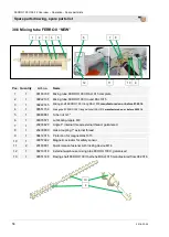
Page 54: ...FERRO II 3 1 00216381 Level sensor KPS1 1 5 m 90 long control plug 10 pin 2 00214853 Washer polyethylene 30x36x1 0 mm 4 1 00083456 Gear motor ZF38 5 5kW 400U RAL1015 manufactured on or before 07 2016...

Page 55: ...ers and hose clamps for CMP and delivery hood 3 1 00270211 Geared motor flat gear 0 75 400V FERRO RAL1015 4 1 00037560 Motor connection cable 1 25 m CEE 4 x 16A 38 3Dosing tube FERRO II Pos Quantity A...

Page 56: ...M14 2 1 00551154 Mixing shaft FERRO 100 II long half shell RAL1015 3 1 00186391 Magnetic safety sensor 2 1S 1 00057992 Magnetic actuator for safety sensor 4 1 20185001 Water flow meter 250 2500 l h c...

Page 57: ...no Name 1 1 00193708 Mixing tube FERRO 100 II RAL1015 complete 2 1 00193357 Mixing tube FERRO 100 II RAL1015 3 1 00193402 Mixing shaft FERRO 100 II RAL1015 4 1 00069797 Bearing bush HM 5 OCTAGON galv...

Page 58: ...4 1 00551154 Mixing shaft FERRO 100 II long half shell RAL1015 manufactured on or before 08 2016 5 1 00080861 Tube nut G 1 6 1 00035571 Lubricating nipple M 8 7 1 20203620 Angle 1 internal thread ext...

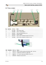
Page 59: ...ERRO II 3 1 00035121 Pump shaft FERRO II RAL1015 4 1 00021025 ROTOR FERRO 5 1 00511614 Pump container FERRO 100 II RAL1015 K Trans 5 1 00186446 Pump container FERRO 100 II RAL1015 IT Pos Quantity Art...

Page 60: ...ocking screw 1 2 galvanised 2 1 20144021 Slide ring gasket set oil sealing unit ZP 3 3 1 20144015 O ring 50 x 2 4 1 20144077 Sealing ring D53 5 x 10 5 T10 5 1 00035128 Adaptor pump FERRO galvanised 6...

Page 61: ...mplete 2 1 00099089 Manometer with plastic inlet housing 0 100 bar 1 VA 3 2 20209920 Hex nut M16 galvanised 4 2 00197917 Tie rods M16 x 550mm galvanised on both sides M16 5 1 00021024 Stator FERRO 5a...

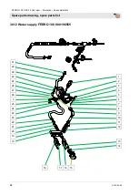
Page 62: ...Part 2 Overview Operation Spare parts lists Spare parts drawing spare parts list 62 2018 03 26 38 10 Water supply FERRO 100 II 00186555 1 2 3 2 4 5 6 21 18 16 20 19 18 17 16 7 8 9 10 11 12 13 14 15 26...

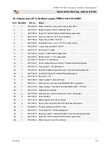
Page 63: ...le nipple 1 x 100 galvanised 12 1 00 02 26 57 T piece 1 internal thread 1 external thread 1 internal thread galvanised 13 1 00 02 36 03 Reduction nipple 1 external thread 1 4 internal thread galvanise...

Page 64: ...rview Operation Spare parts lists Spare parts drawing spare parts list 64 2018 03 26 38 12 Water supply FERRO 100 II 00186555 16 17 16 15 21 22 29 22 24 28 27 26 3 25 24 22 23 22 21 20 19 18 1 2 3 4 5...

Page 65: ...1 external thread with gasket 13 1 20 20 33 13 Tube nipple 1 x 30 galvanised 14 1 00 03 61 18 Reduction nipple 2 external thread 1 internal thread galvanised 15 1 20 20 07 80 Coupling 50 M part 2 inte...

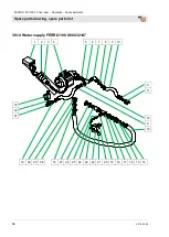
Page 66: ...view Operation Spare parts lists Spare parts drawing spare parts list 66 2018 03 26 38 14 Water supply FERRO 100 II 00232147 1 2 3 4 5 6 7 8 9 10 12 30 29 28 14 27 26 25 24 23 22 21 20 19 18 17 16 15...

Page 67: ...1 20 20 16 90 High pressure suction coupling 1 sleeve with gasket 16 1 20 20 17 00 Gasket of Geka coupling PACKING UNIT PCS 50 17 1 20 20 08 00 Geka coupling 1 external thread PACKING UNIT 10 PCS 18...

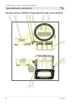
Page 68: ...2 Overview Operation Spare parts lists Spare parts drawing spare parts list 68 2018 03 26 38 16 Water supply FERRO 100 II 00232147 1 2 3 2 4 5 20 19 24 23 22 21 20 6 7 8 9 10 11 12 13 14 15 16 17 18...

Page 69: ...1 1 20 20 33 13 Tube nipple 1 x 30 galvanised 12 1 20 17 17 41 Diaphragm valve 1 type 671 13 2 00 08 08 61 Tube nut G 1 14 1 00 20 61 96 Long thread sleeve 1 x 100 galvanised 15 1 00 02 34 90 Double n...

Page 70: ...O 100 II Part 2 Overview Operation Spare parts lists Spare parts drawing spare parts list 70 2018 03 26 38 18 Control box Art no 00178685 00208092 1 2 3 4 5 6 16 15 14 13 2 12 11 2 13 19 18 14 17 7 8...

Page 71: ...66 10 CEE socket outlet 4 x 16A 6h red 8 1 00 02 20 66 CEE socket outlet 4 x 16A 7h black 500 V 9 1 00 02 20 67 CEE panel mounted socket 5 x 16A 7h sw 10 1 20 42 72 00 Schuko socket outlet 16A blue 11...

Page 72: ...s Spare parts drawing spare parts list 72 2018 03 26 38 19 Control box Art no 00178685 00208092 1 2 3 4 5 6 7 8 2 9 10 4 11 21 20 2 19 11 4 19 4 11 2 13 11 2 13 14 15 23 17 2 18 4 18 2 17 4 22 2 9 12...

Page 73: ...element 1 opener M22 EK01 10 6 00 05 38 81 Luminous element white 12 30V 11 6 00 05 38 35 Contact element 1 closer M 22 EK 10 12 1 00 18 63 72 Step switch 0 6 1 pin 13 4 00 05 38 39 Pushbutton without...

Page 74: ...Overview Operation Spare parts lists Spare parts drawing spare parts list 74 2018 03 26 38 20 Control box article number 00178685 internal 1 2 3 4 19 18 13 17 13 16 15 13 14 13 14 11 12 13 14 6 7 6 5...

Page 75: ...2 5 Q2 Q3 9 1 00 04 35 51 Motor protection switch 16 20A PKZM 0 20 Q5 10 1 00 04 26 02 Motor protection switch 10 16A PKZM 0 16 Q4 11 1 20 45 31 01 Operation hour counter 42V P1 12 1 00 02 21 53 Therm...

Page 76: ...2 Overview Operation Spare parts lists Spare parts drawing spare parts list 76 2018 03 26 38 21 Control box Art no 00208092 internal 1 2 3 4 19 18 13 17 13 16 15 13 14 13 14 11 12 13 14 20 6 7 6 5 9...

Page 77: ...ection switch 1 6 2 5A PKZM 0 2 5 Q2 Q6 9 1 00 04 35 51 Motor protection switch 16 20A PKZM 0 20 Q5 10 1 00 04 26 02 Motor protection switch 10 16A PKZM 0 16 Q4 11 1 20 45 31 01 Operation hour counter...

Page 78: ...RO 100 II Part 2 Overview Operation Spare parts lists Spare parts drawing spare parts list 78 2018 03 26 38 23 Star wheel lock FERRO II complete RAL1015 Article number 00035135 1 2 3 4 5 6 7 9 11 8 9...

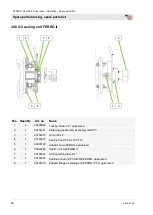
Page 79: ...2 00 03 90 41 Sponge rubber buffer FERRO 4 1 00 26 65 24 Torque supports for star wheel lock for Neudecker Joliltz gear motor RAL1015 5 1 20 70 63 10 Rubber seal D 450x360x4 6 8 00 03 64 88 Wear plat...

Page 80: ...FERRO without 1 00 51 29 72 Float gauge valve MS incl float gauge cmpl 2 00 51 63 22 Disc 55x34x1 5 VA 1 20 20 36 22 Angle 1 internal thread galvanised 1 20 20 08 00 Geka coupling 1 external thread 1...

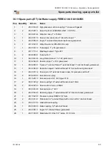
Page 81: ...vanised 2 1 00023837 Rubber sheet 50 x 2 x 320 without web 3 2 00023274 Hex screw M14 x 55 galvanised 4 4 20209011 Washer B 15 galvanised 5 1 00034742 Connection pieces for tensioning 6 1 00023430 Tur...

Page 82: ...isposal 52 Do not load pump motor 48 Do not load the pump unit 48 Dosing tube FERRO II 55 Drain water from pump container 31 EMERGENCY OFF push button 26 EMERGENCY STOP situation end of work or interr...

Page 83: ...of emergency 34 Shutdown in case of emergency 34 Silo mounting 81 Sound power level 10 Spare parts ET list Water supply FERRO 100 II 00186555 63 65 Spare parts ET list Water supply FERRO 100 II 00232...

Page 84: ...parts lists 84 2018 03 26 PFT ALWAYS AT YOUR SITE Knauf PFT GmbH Co KG P O Box no 60 97343 Iphofen Einersheimer Stra e 53 97346 Iphofen Germany Phone 49 9323 31 760 Fax 49 9323 31 770 Technical hotli...

Reviews: