background image


____________________________________________________________________________________________________________  

PFT G 5 c FU 230 

11


Basic Safety Instructions 

01.2005 

____________________________________________________________________________________________________________  

________________________________________________________________________________________  


Knauf PFT GmbH & Co. KG 


Telephone 

09323 / 31-760


PO Box 60 


Telefax 

09323 / 31-770


D-97343 Iphofen 


Internet 

www.pft.de


________________________________________________________________________________________  


1. 

Follow  all  safety  instructions  and  danger  warnings  on  the  machine.  Ensure  that  all 
instructions are kept legible! 

2. 

Inspect the machine for visible damage and defects at least once every shift! If you notice 
any  safety-threatening  alterations  to  the  machine  or  its  operating  behavior,  stop  the 
machine immediately and notify your supervisor! 

3. 

Do not attempt to modify the machine in any way which may impair its safety without first 
consulting your machine dealer! This also applies to the installation of unchecked “safety 
devices”! 

4. 

All spare parts must comply with the technical requirements of the manufacturer. This is 
guarantied for all original PFT parts! 

5. 

Only trained or authorized personnel should operate the machine. Clearly define all lines 
of responsibility for operation, equipping, service and maintenance! 

6. 

Personnel  undergoing  training  should  only  be  allowed  to  operate  the  machine  under  the 
supervision of experienced personnel! 

7. 

All electrical work should be carried out by a qualified electrician or by trained personnel 
under  the  supervision  of  a  qualified  electrician  and  should  comply  with  electro-technical 
regulations. 

8. 

Observe  all  instructions  for  turning  the  machine  on  and  off.  Watch  control  lamps  for 
signals. 

9. 

If  the  machine  is  completely  switched  off  for  maintenance  and  repair  work,  it  must  be 
ensured that it cannot be switched back on accidentally (for example, lock the main switch 
and remove the key, or attach a warning sign to the main switch). 

10.  Before cleaning the machine with a water jet, seal all openings through which water could 

enter, thereby impairing the safety and proper functioning of the machine (electric motors 
and control boxes). After cleaning, remove all covers. 

11.  Only use original fuses with prescribed amps! 

12.  Control box must be closed during operation! 

13.  Disconnect  the  machine  from  any  external  energy  source  before  you  relocate  it,  even  if 

you are only moving it a short distance. Prior to putting the machine back into service, it 
should be connected to the mains correctly. 

14.  Set  up  the  machine  on  stable  and  horizontal  ground  and  secure  it  against  unintentional 

movements. 

15.  Lay out the conveying lines safely. Do not rest them on sharp edges! 

16.  Depressurize all conveying systems before opening conveying lines! 

17.  When  unblocking  hoses,  stand  away  from  the  machine  to  avoid  injury  through  high-

pressure discharges of mortar. Always wear safety goggles. No other persons should be 
near the machine.


18.  If the permanent noise level exceeds 85 dB(A), appropriate noise protection devices must 

be provided. 

19.  If  required,  wear  the  following  protective  clothing  while  spraying:  Safety  goggles,  safety 

shoes, safety clothing, gloves, protective skin cream and respirator mask. 

20.  Have the machine inspected by a qualified person. This should however happen at least 

once a year. 


Summary of Contents for G 5 c FU 230V

Page 1: ...OPERATING INSTRUCTIONS BAL NO 00 07 45 22 MIXING PUMP PFT G 5 c FU 230V WE KEEP THINGS MOVING...

Page 2: ...forward this document even excerpts without written authorization by us All technical specifications diagrams etc are subject to copyright protection All rights errors and modifications reserved by K...

Page 3: ...pany with a name that has exemplified quality The PFT G 5 c FU 230 mixing pump uses state of the art technology It was designed in a task optimized way so that it can be a trustworthy aid for rough co...

Page 4: ..._______________________________________________________________________________________ ________________________________________________________________________________________ Knauf PFT GmbH Co KG Te...

Page 5: ...indispensable task of all technicians delivering the PFT G 5 c FU 230 mixing pump is the inspection of the machine settings at the end of the first spraying phase The factory settings can be changed d...

Page 6: ...Telefax 09323 31 770 D 97343 Iphofen Internet www pft de ________________________________________________________________________________________ General information 1 PFT sales information 3 Table o...

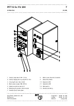
Page 7: ...ne 09323 31 760 PO Box 60 Telefax 09323 31 770 D 97343 Iphofen Internet www pft de ________________________________________________________________________________________ 1 Mixing pump motor 11 Pump...

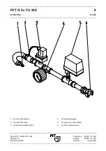
Page 8: ..._________________________________________________ Knauf PFT GmbH Co KG Telephone 09323 31 760 PO Box 60 Telefax 09323 31 770 D 97343 Iphofen Internet www pft de _______________________________________...

Page 9: ...uf PFT GmbH Co KG Telephone 09323 31 760 PO Box 60 Telefax 09323 31 770 D 97343 Iphofen Internet www pft de ________________________________________________________________________________________ 1 S...

Page 10: ...__________ ________________________________________________________________________________________ Knauf PFT GmbH Co KG Telephone 09323 31 760 PO Box 60 Telefax 09323 31 770 D 97343 Iphofen Internet...

Page 11: ...ng mixing pump for pre mixed ready to use dry mortar It can be filled either with bagged material or using the delivery or injection hood Please observe the processing guidelines of the material manuf...

Page 12: ...formation NOTE Special information for running the machine efficiently WARNING Special information regulations and restrictions concerning the prevention of damage WARNING The machine should only be u...

Page 13: ...d personnel under the supervision of a qualified electrician and should comply with electro technical regulations 8 Observe all instructions for turning the machine on and off Watch control lamps for...

Page 14: ...mpressor safety valve 1 5 bar against closed air pipe factory setting secured Pressure reducing valve 1 9 bar for maximum flow at water manifold 1000 l min Motor protection switch Output Setting value...

Page 15: ...nveying pressure Early detection of clogging or overloading of pump motor Early detection of clogging or overloading of pump motor Establishes zero pressure Contributes significantly to the safety of...

Page 16: ...er should be 5 to 10 bar above the expected mortar conveying pressure An adverse position of the screw pump in the liner will result in water flowing back to the hopper accompanied by a distinct gurgl...

Page 17: ...water intake to vent and clean the hose line Close water intake Connect water hose to inlet of water manifold water pump Close drainage valves on water manifold at a water pressure below 2 5 bar the...

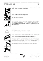
Page 18: ..._______________________________________________________________ Connect control box to power supply Now the following steps must be carried out Turn on the main switch Warning The protective grille mu...

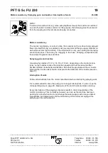
Page 19: ...of the mixing area s lower water connection so that excess water can be drained The control circuit must be interrupted by removing the blind plug IMPORTANT The TWISTER D 6 3 pump always requires swam...

Page 20: ...ssor insert plug Connect all required mortar hoses to each other and flush with water to avoid hose blocks do not leave water in hoses To do so use cleaner coupling in tool bag If mortar quality is un...

Page 21: ...apply material on wall surfaces from top to bottom If the material is too dry even mixing and spraying cannot take place There may be clogging in the hose Pumping components are thus subject to great...

Page 22: ...f compressor 3 pull plug and open tap on spraying gun Disconnect mortar hose only when depressurized Release snap lock 1 on motor tilt flange and tilt motor Remove and clean mixing shaft 2 Clean mixin...

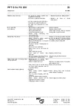
Page 23: ...one 09323 31 760 PO Box 60 Telefax 09323 31 770 D 97343 Iphofen Internet www pft de ________________________________________________________________________________________ Close water intake valve De...

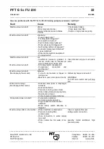
Page 24: ...level defective Fuses defective Water safety switch misadjusted Pump jammed Machine does not start Air Insufficient pressure gradient in remote control due to blocked air pipe or blocked air nozzle t...

Page 25: ...If this doesn t help clean or replace mixing tube dry and restart Mortar flow thin thick not enough water Water pressure safety switch misadjusted or defective Mixing shaft defective no original PFT...

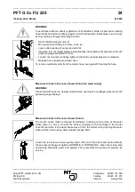
Page 26: ...foil Reverse run 3 water intake is automatically interrupted until pressure at mortar pressure gauge has fallen to 0 bar Loosen nut on pressure flange lightly so that entire residual pressure is relea...

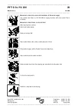
Page 27: ...www pft de ________________________________________________________________________________________ Measures to take in the case of a breakdown of the water supply Use suction inlet item no 00 00 69 0...

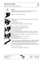
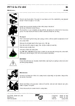
Page 28: ...is now completely empty with the exception of a small rest in the screw pump The machine must however still be started carefully the next day Transport Prior to transporting the mixing pump using a cr...

Page 29: ...item no 00 00 85 45 The PFT delivery hood is for feeding dry material into the PFT G 5 c FU 230 mixing pump directly from the silo container If the material hopper of the PFT G 5 c FU 230 mixing pump...

Page 30: ...______________________________________________________________________________________ ________________________________________________________________________________________ Knauf PFT GmbH Co KG Tel...

Page 31: ...______________________________________________________________________________________ ________________________________________________________________________________________ Knauf PFT GmbH Co KG Tel...

Page 32: ...___________________________________________________________________________________________________ ________________________________________________________________________________________ Knauf PFT G...

Page 33: ...kW 12U m RAL2004 NORD 16 1 20 42 41 46 Motor connecting cable 1 0 m 4 wire end sleeves and ring eyelet 4 mm 17 2 20 20 78 02 Skt screw M8 x 50 DIN 933 zinc pl 18 2 20 20 72 00 Nut M8 DIN 985 zinc pl...

Page 34: ..._________________________________________________________________________________________________ ________________________________________________________________________________________ Knauf PFT Gmb...

Page 35: ...D 4 5 with ring 13 1 20 10 12 02 Pin motor flange zinc pl 14 2 20 20 99 21 Nut M16 DIN 6331 zinc pl 15 2 20 20 11 00 Geka coupling 1 IG 16 3 20 20 17 00 Gasket Geka coupling 17 1 20 20 16 50 Geka cou...

Page 36: ..._________________________________________________________________________________________________ ________________________________________________________________________________________ Knauf PFT Gmb...

Page 37: ...omatic plumb level DIL 0M 42 V 7 1 20 44 81 20 Switching relay 42 V 2 changer 8 1 20 45 04 10 Auxiliary contact 31 DIL M assembly 9 1 00 03 75 92 Frequency converter 230 V 4 KW 17 6 A programmed 10 1...

Page 38: ..._________________________________________________________________________________________________ ________________________________________________________________________________________ Knauf PFT Gmb...

Page 39: ...Contact element 1 closer M22 6 4 00 05 38 34 Fixation adapter for switch elements 7 1 00 05 38 78 Selector switch toggle sensing 0 latching M22 8 1 00 05 38 39 Pressure switch without sensor plate M2...

Page 40: ...__________________________________________________________________________________________________ ________________________________________________________________________________________ Knauf PFT Gm...

Page 41: ...reduced 1 2 1 4 AG no 245 zinc pl 13 1 20 44 76 00 Air safety switch type FF4 4 0 22 4 bar 14 1 20 20 36 10 Curved section 1 2 IG AG no 92 zinc pl 15 1 20 20 09 00 Geka coupling 1 2 AG 16 1 20 15 20 0...

Page 42: ..._________________________________________________________________________________________________ ________________________________________________________________________________________ Knauf PFT Gmb...

Page 43: ...essor 220 V 6 1 00 04 77 30 Compressor DT4 16 230 V 50 60 Hz cable 0 6m and earthling plug 7 1 20 42 46 00 Earthling plug 16 A black no 10754 8 1 20 44 76 00 Safety switch type FF4 4 0 22 4 bar 9 1 20...

Page 44: ...____________________________________________________________________________________________________ ________________________________________________________________________________________ Knauf PFT...

Page 45: ...__________________ Item Qty Item no Article description 1 1 00 05 08 69 High pressure pump G 54 E 230 V PQm 60 lateral 2 1 00 00 14 99 High pressure pump AV 3 PQm 60 230 V 1phase 3 1 20 20 50 00 Reduc...

Page 46: ...er consumption Pump motor at maximum load 13 9 A at 230 V Star wheel motor at maximum load 1 8 A at 230 V Electrical connection 230 V 1ph 16 A Fuse protection min 16 A C slow blow Power unit min 10 kV...

Page 47: ......

Page 48: ...E KEEP THINGS MOVING Knauf PFT GmbH Co KG PO Box 60 D 97343 Iphofen Einersheimer Strasse 53 D 97346 Iphofen Telephone 0 93 23 31 760 Telefax 0 93 23 31 770 Email info pft iphofen de Internet www pft d...

Reviews: