background image

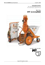
PFT G 5 SUPER

  Operating Manual 

Issued 11.2008 

Knauf PFT GmbH & Co.KG  

13 

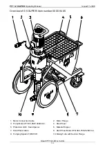
Overview of G 5 SUPER: ltem number 00 00 84 05 


1.  Motor Connection Cable 

2.  Motor Flange 

3.  Pump Motor ZF 38 5,5KW 400U/min. 

4.  Star Wheel 

5.  Protection Grill + Sack Opener 

6.  Material Hopper 

7.  Star Wheel Cable 

8.  Star Wheel Motor ZFQ 38 0,75KW 28U/min. 

9.  Pumping System TWISTER 

10. Mixing Tube with Suction Flange 


Summary of Contents for G 5 SUPER

Page 1: ...ER Operating Manual Issued 11 2008 Knauf PFT GmbH Co KG 1 OPERATING MANUAL ltem number of operating manual 00 01 19 27 ltem number of machine parts list 00 00 79 40 Mixer Pump PFT G 5 SUPER WE KEEP TH...

Page 2: ...PFT GmbH Co KG 2 It is prohibited to forward this document even excerpts without our written authorisation All technical specifications diagrams etc are subject to copyright law All rights errors and...

Page 3: ...correctly and handled with care It is prohibited to forward this document even excerpts without our written authorisation All technical specifications diagrams etc are subject to copyright law All rig...

Page 4: ...9 Settings 19 Mortar pressure 20 PFT pump components 20 Checking the conveying pressure and back pressure 21 Pump System adjustable 22 Start up 23 Setting the water factor 25 Procedures at the End of...

Page 5: ...d G 5 SUPER part no 00008261 50 Sare parts list control box external part no 00007134 52 Spare parts list control box internal part no 00007134 54 List of spraying guns hoses tool kits and spraying ca...

Page 6: ...ld 5 Connection for water supply water manifold booster pump 6 Connection for air manifold air hose 7 Connection for air hose finishing plaster device 8 Connection for mixing tube mortar pressure gaug...

Page 7: ...ld not be touched without protective gloves Waste oil Proper handling Only pour waste oil in the disposal container if it consists purely of oil Do not pour in any mixtures such as mixed benzine and o...

Page 8: ...must be taken to ensure that it cannot be switched back on accidentally for example lock the main switch and remove the key or attach a warning sign to the main switch 10 Before cleaning the machine w...

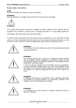
Page 9: ...a long time to come WARNING The following terms and symbols are used in this manual for particularly important information WARNING The machine should only be used if it is in flawless technical condit...

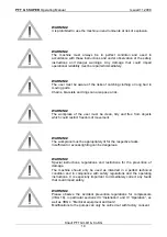
Page 10: ...t be clean tidy and free from objects which could restrict freedom of movement WARNING The workplace must be appropriately lit for the respective tasks Insufficient or excess lighting can be dangerous...

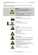
Page 11: ...not reach into the machine while it is running Maximum pressure Do not exceed the maximum pressure Hand injury Keep hands away from areas displaying this warning symbol There is a risk of hands becomi...

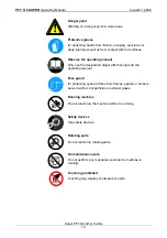
Page 12: ...ual Only use the designated object after having read the operating manual Face guard for protecting eyes and face from flames sparks or embers as well as from hot particles or exhaust gases Running ma...

Page 13: ...SUPER ltem number 00 00 84 05 1 Motor Connection Cable 2 Motor Flange 3 Pump Motor ZF 38 5 5KW 400U min 4 Star Wheel 5 Protection Grill Sack Opener 6 Material Hopper 7 Star Wheel Cable 8 Star Wheel Mo...

Page 14: ...Knauf PFT GmbH Co KG 14 Overview of CADDY G 5 SUPER ltem number 00 00 82 15 1 Controll Box G 5 SUPER 2 Socket for Mains 32A 3 Housing for manifold G 5 SUPER 4 Water Connection from Mains or Tank 5 Wat...

Page 15: ...e 5 Empty No Material 6 Display Lamp On Off 7 Display Lamp Fault in System 8 Socket Mixing Pump 9 Socket Vibrator 16A 10 Socket Compressor 16A 11 Socket Star Wheel 16A 12 Schuko Socket 230V 16A fuse 1...

Page 16: ...pressor Switch 4 Air to Spraying Gun 5 High Pressure Pump AV 3 6 Water Saftey Switch 7 Water Inlet Filter 8 Water Connection form Mains or Tank 9 Pre valve Pressure 10 Pre valve Pressure 11 Water Outl...

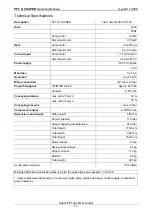
Page 17: ...R D6 3 Z approx 22 l min Variabel 6 85 l min Conveying distance max with 25 mm 30 m max with 35 mm 50 m Conveying pressure max 30 bar Compressor output 0 25 Nm min Dimensions and weight Filling height...

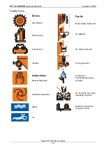
Page 18: ...r Wheelr Faults Motor Saftey Switch off Water Pump No Material Compressor No Water Pressure Vibrator Wrong Direction Instructions Manual Operation At Subzero Temperatures empty all water Automatic Ope...

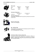
Page 19: ...etting and secured with knurled screw Pressure reducing valve 1 9 bar at max throughput Gap Air Nozzle Pipe The gap between the air nozzle tube and spraying cap should correspond to the diameter of th...

Page 20: ...clogging or overloading of pump motor Establishment of zero pressure Significant contribution to the safety of the operating personnel Durability of the pump components PFT pump components Warning Dur...

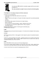
Page 21: ...replaced Check back pressure Maintain a back pressure of approx 14 bar through the rotor stator pump TWISTER D6 3 in the hose NOTE The testing pressure with water should be approx 5 10 bar above the...

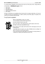
Page 22: ...uality of the mortar you are producing will also suffer Pump System adjustable While using adjustable pumps see to it that the main switch is switched off during assembly the stator protrudes evenly a...

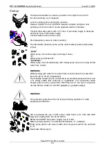
Page 23: ...Water pump runs simultaneously with mixing pump if you are using stored water from a tank WARNING While working with water from a tank fit the suction inlet with a water filter Item No 20 47 50 00 dea...

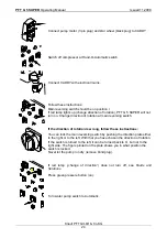
Page 24: ...at main reversing switch If the direction of rotation is wrong follow these instructions You can lock the main reversing switch by pushing the direction plate either to the right or to the left With...

Page 25: ...you detect irregularities but instead wait until the consistency of the material emerging at the spray gun has self adjusted Connect the water hose of the water flow meter to the top water inlet of th...

Page 26: ...pump and is switched on and off with the air pressure control or remote control WARNING Do not remove protection grill when the machine is ready for operation Couple the mortar pressure gauge to the...

Page 27: ...ality add approx 3 liters of smooth flowing lime or gypsum sludge to the first hose after the machine WARNING Ensure right and clean connections of couplings Connect hoses with the mortar pressure gau...

Page 28: ...nts are thus subject to greater wear and tear Spraying Guns and Caps Use spraying caps of 10 12 14 16 oder 18 mm depending on the mortar consistency Larger caps reduce the projection speed and the reb...

Page 29: ...Remove plug on CADDY Disconnect mortar hose only when depressurized To clean connect the hoses including the mortar pressure gauge to the water inlet valve with the help of the transition adaptor in...

Page 30: ...green button on run for approx 5 10 secs until mixing tube is clean Press red button off remove cleaner Fit in clean mixing shaft Shut motor flange and lock snaps Empty the material hopper if the mac...

Page 31: ...on reverse button 3 till reading on mortar pressure gauge is at 0 bar water supply is automatically interrupted Loosen nuts on pressure flange slightly so that residual pressure can escape To remove r...

Page 32: ...y and prepare it for operation again Measures for Water Supply Failure Use suction inlet Item No 00 00 69 06 to supply the machine with clean water Measures for Suzero Temperatures Ater cleaning machn...

Page 33: ...ed air will now blow water out of the manifold at 1 5 bar approx for 1 minute Swivel the entire pumping unit upwards and empty the mixing pump Disconnect mortar hoses and empty them Apart from a small...

Page 34: ...disconnecting them Watch the readings on the mortar pressure gauge Maintenance Clean compressor filter after every operation if necessary by knocking out dirt Replace filter if it is heavily soiled N...

Page 35: ...sation and mixing of the material Direct drive via the rotor tenons Volume of approx 1 2 l All guidelines of the material manufacturer must be observed ROTOQUIRL II cpl with size 35 coupling item no 2...

Page 36: ...orking Too much thick material in hopper or mixing zone Empty hopper by half and start up again Material in pumping zone too dry CAUTION Water does not flow Solenoid valve Hole in membrane blocked Mag...

Page 37: ...ty Clamp faulty oval Inner side of mortar hose faulty Replace mortar hose Rotor too deep in pressure flange Check mixing shaft and hauling bracket not original PFT parts Water rises in mixing tube Bac...

Page 38: ...PFT G 5 SUPER Operating Manual Issued 11 2008 Knauf PFT GmbH Co KG 38 Spare parts list for chassis G 5 SUPER part no 00008223...

Page 39: ...ic bush MS for G 4 locking lever 20 1 20 20 72 10 Safety nut M 10 DIN 985 galv 21 2 20 20 78 00 Hex screw M 8 x 30 DIN 933 galv 22 2 20 20 72 00 Safety nut M 8 DIN 985 galv 23 2 20 56 66 15 Folding ha...

Page 40: ...PFT G 5 SUPER Operating Manual Issued 11 2008 Knauf PFT GmbH Co KG 40 Spare parts list geard motor mixing tube...

Page 41: ...6 DIN 934 galv 13 1 20 10 35 10 Mixing shaft reinforced for G 4 G 5 RAL2004 14 1 00 09 12 89 Cleaning shaft galv 15 1 20 10 23 20 Mixing tube cleaner for D and R pumps 16 1 00 00 83 61 Motor connectio...

Page 42: ...PFT G 5 SUPER Operating Manual Issued 11 2008 Knauf PFT GmbH Co KG 42 Spare parts list pump unit mortar pressure gauge...

Page 43: ...1 Collar nut M 16 DIN 6331 galv 7 1 00 00 17 92 Double nipple 1 1 4 x 60 no 23 galv 8 1 20 20 07 90 Coupling 35 female 1 1 4 int thread with gasket 9 1 00 09 90 88 Gauge with plastic inlet housing 0 1...

Page 44: ...PFT G 5 SUPER Operating Manual Issued 11 2008 Knauf PFT GmbH Co KG 44 Spare parts list chassis caddy compressor K2N and manifold box...

Page 45: ...ng for manifold G 5 RAL9002 11 1 00 02 21 21 Door manifold box G 5 RAL9002 structure 12 2 20 20 86 03 Fastener with cap 20s x N 2 7 13 2 00 00 82 54 Replacement wheel 230x85 cover RAL2004 14 2 20 20 6...

Page 46: ...PFT G 5 SUPER Operating Manual Issued 11 2008 Knauf PFT GmbH Co KG 46 Spare parts list water manifold G 5 SUPER part no 00008260...

Page 47: ...1 20 20 31 07 Nipple 1 2 ext thread flat with nut3 4 int thread 15 1 20 20 51 10 Reducing nipple 3 4 ext thread 1 2 int thread no 241 galv 16 1 00 06 21 26 Long threaded socket 3 4 x 90 galv 17 1 20 2...

Page 48: ...PFT G 5 SUPER Operating Manual Issued 11 2008 Knauf PFT GmbH Co KG 48...

Page 49: ...16 Support red bronze manifold block CADDY G 5 RAL2004 44 1 00 03 92 86 Manifold block red bronze DK 06 FN 1 2 E 45 1 00 04 04 26 Inlet for control valve cpl for manifold block red bronze 46 1 00 04 0...

Page 50: ...PFT G 5 SUPER Operating Manual Issued 11 2008 Knauf PFT GmbH Co KG 50 Spare parts list air manifold G 5 SUPER part no 00008261...

Page 51: ...93 15 Washer B 21 DIN 125 galv 9 1 00 00 82 59 Counter flow valve 3 8 int thread 10 1 20 44 76 00 Pressure switch type FF4 4 0 22 4bar 11 1 20 44 76 00 Pressure switch type FF4 4 0 22 4bar 12 1 00 00...

Page 52: ...PFT G 5 SUPER Operating Manual Issued 11 2008 Knauf PFT GmbH Co KG 52 Sare parts list control box external part no 00007134...

Page 53: ...unit 17 1 00 05 38 43 Front unit for press button blue reset M 22 18 1 00 05 38 30 Membrane round for pressure switch 19 1 00 10 21 36 Indicator lamp LED 48 V AC DC red 20 3 00 10 21 37 Control lamp...

Page 54: ...PFT G 5 SUPER Operating Manual Issued 11 2008 Knauf PFT GmbH Co KG 54 Spare parts list control box internal part no 00007134 C C C C C C C...

Page 55: ...ime lag relay 42 V 0 5 10 sec 7 1 00 00 17 58 Impulse relay 42 V 10 sec 8 1 20 44 73 10 Contactor DIL ER 31 42 V 9 1 00 01 20 40 Auxillary contact 11 DIL E 10 2 00 00 93 71 Motor protection switch 10...

Page 56: ...PFT G 5 SUPER Operating Manual Issued 11 2008 Knauf PFT GmbH Co KG 56 List of spraying guns hoses tool kits and spraying caps...

Page 57: ...1 00 06 23 83 Spraying cap S 14 mm black 3 1 20 19 10 00 Spraying cap 16 mm packing unit 10 pieces 4 1 00 02 16 66 Tool kit mixing pump conveying pump 5 1 20 21 10 03 Water air hose 1 2 16 m with Geka...

Page 58: ...PFT G 5 SUPER Operating Manual Issued 11 2008 Knauf PFT GmbH Co KG 58 Circuit Diagramm...

Page 59: ...PFT G 5 SUPER Operating Manual Issued 11 2008 Knauf PFT GmbH Co KG 59 Circuit Diagramm...

Page 60: ...PFT G 5 SUPER Operating Manual Issued 11 2008 Knauf PFT GmbH Co KG 60 Circuit Diagramm...

Page 61: ...PFT G 5 SUPER Operating Manual Issued 11 2008 Knauf PFT GmbH Co KG 61 Circuit Diagramm...

Page 62: ...ile in mixing area for wear Hauling bracket Check hauling bracket for wear Protective grille Is protective grille still evenly flat Frame Check all welded seams Frame Check whether all screwed joints...

Page 63: ...PFT G 5 SUPER Operating Manual Issued 11 2008 Knauf PFT GmbH Co KG 63 Notes...

Page 64: ...f PFT GmbH Co KG 64 WE KEEP THINGS MOVING Knauf PFT GmbH Co KG Postfach 60 97343 Iphofen Einersheimer Stra e 53 97346 Iphofen Germany Phone 49 9323 31 760 Fax 49 9323 31 770 Technical assistance hotli...

Reviews: