PFT G 5 SUPER
Operating Manual
Issued 11.2008
Knauf PFT GmbH & Co.KG
45
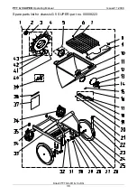
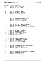
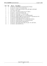
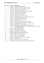
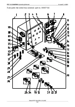
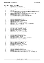
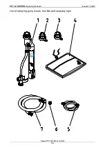
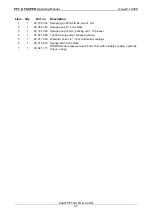
Ltem. Qty Part
no. Description
1
1
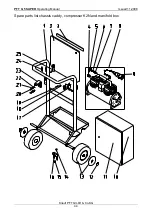
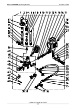
00 00 82 18 Chassis CADDY G 5 RAL2004
2
1
00 00 83 87 Rubber guard for CADDY G 5
3
1
00 00 83 88 Clamping strip for rubber guard CADDY G5 RAL2004
4
1
20 20 20 00 EWO coupling female 1/4" ext. Thread non-blocking
5
1
20 20 36 50 Angle 1/4" int. thread - ext. thread no. 92 galv.
6
1
20 13 47 00 Sealing ring 13 x 20 x 2
7
1
20 13 12 00 Safety valve 1/4" 3.5bar with washer
8
1
00 00 85 64 Air compressor K2 cable 750mm long with CEE-plug
9
1
20 42 79 00 Plug CEE 4 x 16A 6h red no. 252
10
1
00 00 82 17 Housing for manifold G 5 RAL9002
11
1
00 02 21 21 Door manifold box G 5 RAL9002 structure
12
2
20 20 86 03 Fastener with cap 20s x N 2 7
13
2
00 00 82 54 Replacement wheel 230x85 cover RAL2004
14
2
20 20 61 00 Hex. screw M8 x 20 DIN 933 galv.
15
2
20 20 72 00 Safety nut M 8 DIN 985 galv.
16
1
00 00 82 20 Support for water coupling G 5 RAL2004
17
1
00 00 88 69 Support with grip on right for CADDY G 5 RAL2004
18
6
20 20 72 00 Safety nut M 8 DIN 985 galv.
19
6
20 20 78 10 Hex. screw M8 x 25 DIN 933 galv.
20
2
20 20 61 00 Hex. screw M8 x 20 DIN 933 galv.
21
2
20 20 93 13 Hex. screw M8 x 20 DIN 933 galv.
22
2
20 20 72 00 Safety nut M 8 DIN 985 galv.
23
1
00 00 82 19 Support for water flow meter G 5 RAL2004
24
2
00 00 93 12 Clamping plate M 8 LA = 25mm
25
1
00 00 88 68 Support with grip on left CADDY G 5 RAL2004
Summary of Contents for G 5 SUPER
Page 48: ...PFT G 5 SUPER Operating Manual Issued 11 2008 Knauf PFT GmbH Co KG 48...
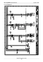
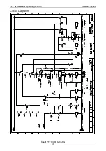
Page 58: ...PFT G 5 SUPER Operating Manual Issued 11 2008 Knauf PFT GmbH Co KG 58 Circuit Diagramm...
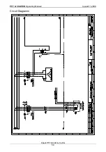
Page 59: ...PFT G 5 SUPER Operating Manual Issued 11 2008 Knauf PFT GmbH Co KG 59 Circuit Diagramm...
Page 60: ...PFT G 5 SUPER Operating Manual Issued 11 2008 Knauf PFT GmbH Co KG 60 Circuit Diagramm...
Page 61: ...PFT G 5 SUPER Operating Manual Issued 11 2008 Knauf PFT GmbH Co KG 61 Circuit Diagramm...
Page 63: ...PFT G 5 SUPER Operating Manual Issued 11 2008 Knauf PFT GmbH Co KG 63 Notes...

