background image

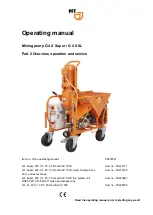
Mixing pump G 4 X Super / G 4 X XL / Part 2 Overview, operation and service

General information

1

General information

1.1

Information regarding the operating manual

This operating manual provides important information and instruc-

tions on the correct use of the machine. A prerequisite for safe

working is the observance of all stated safety guidelines and

instructions.
Furthermore, the local accident prevention guidelines and general

safety instructions for the application area of the device are to be

adhered to.
Read the operating manual thoroughly before starting any work!

It is a part of the product and has to be kept near the device and

easily accessible to the personnel at all times.
If the device is given to third parties, also include the operating

manual.
The figures in this manual are for presentation purposes of facts,

not necessarily to scale and may slightly differ from the actual

model of the device.

1.2

Division

The operating manual is divided into 2 books:

Part 1 Safety/drinking water protection

General safety instructions mixing pumps/conveying pumps
Item no.: 00172709

Part 2 Overview, operation and service (this manual).

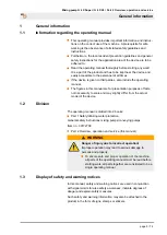
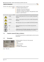
WARNING

Danger of injury due to incorrect operation!

Improper operation may lead to serious damage to

persons and property.

To ensure safe and proper operation of the machine,

all parts of the operating manual must be read before

starting work; all parts together are considered to be a

single operating manual.

1.3

Display of safety and warning notices

In this manual, safety and warning notices are used in conjunction

with signal words to raise safety awareness, indicate degrees of

danger and explain safety measures.
Such safety and warning information may also be attached to the

product in the form of signs, stamps or stickers.

page 5 / 72

Summary of Contents for G4X Super

Page 1: ...Hz with AV 1000 Item no 00414171 G 4 Super 400 V 3 Ph 50 Hz with AV 1000 water hose air hose 40 m and accessories Item no 00414189 G 4 Super 400 V 3 Ph 50 Hz with AV 1000 fine plaster unit DN25 360 S1...

Page 2: ...oduction of this document exploitation or communication of its contents are prohibited unless expressly autho rised Violations may lead to damage compensation All rights are reserved in the event of p...

Page 3: ...and pump 23 4 5 4 Water manifold 23 4 5 5 Air compressor 24 4 5 6 Mortar pressure gauge 24 4 6 Connections 24 4 7 Operating modes 25 4 8 Accessories 26 5 Operation 28 5 1 Safety 28 5 1 1 Safety rules...

Page 4: ...1 Remove connection cable 61 6 2 Environmental protection 61 6 3 Maintenance plan 62 6 4 Maintenance work 62 6 4 1 Implementation by a service techni cian 62 6 4 2 Air filter compressor 63 6 4 3 Plas...

Page 5: ...al are for presentation purposes of facts not necessarily to scale and may slightly differ from the actual model of the device 1 2 Division The operating manual is divided into 2 books Part 1 Safety d...

Page 6: ...described Warning Death or serious injury may occur if you do not take the precautions described Caution Minor injury may occur if you do not take the precautions described Note Property damage may oc...

Page 7: ...000 14 EC Internal production control as per article 14 paragraph 2 in connection with annex V This declaration only refers to the machine in the state in which it has been placed on the market Parts...

Page 8: ...ral non flammable gases Maximum operating pressure initial pressure 16 bar After pressure infinitely adjustable from 1 5 to 6 bar Smallest possible initial pressure 2 5 bar Minimum pressure gradient i...

Page 9: ...Only use the flowmeter as intended Always adhere to the usage directives of the material manufacturer Strictly follow all instructions in this operating manual We accept no responsibility for damages...

Page 10: ...technically perfect condition as well as for its intended use and while taking into account the safety and hazard information in the operating manual In particular faults that can impair safety must b...

Page 11: ...tallation is intended The air compressor must be set up so that no hazardous admixtures such as solvents vapours dusts or other harmful substances can be sucked in The device should be positioned only...

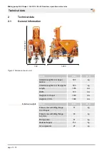
Page 12: ...Detail Value Unit Unladen weight G 4 X Super approx 308 kg Unladen weight G 4 X XL approx 365 kg Length 1200 mm Width 720 mm Height G 4 X Super 1530 mm Height G 4 X XL 1660 mm Individual weights Detai...

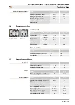
Page 13: ...kW 2 2 A Q5 6 05 kW 11 A Pump motor 7 5 kW 15 A Q6 Compressor 0 9 kW 1 8 A Q2 Water pump 0 37 kW 1 7 A Q4 Water connection Detail Value Unit Operating pressure minimum 2 5 bar Connection inch 2 3 Oper...

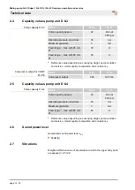
Page 14: ...composition and consistency Compressor output for COMP M 250 Detail Value Unit Compressor output 0 25 Nm min 2 5 Capacity values pump unit D 6 4 Pump capacity D 6 4 Detail Value Unit Pump capacity ap...

Page 15: ...e is danger to life from falling parts or uncontrolled swinging parts Therefore Never step under suspended loads Observe the instructions regarding the provided anchorage points Do not attach to proje...

Page 16: ...n accordance with the transport conditions to be expected Only environmentally friendly materials were used for the packaging The packaging should protect the individual components until the assembly...

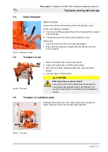
Page 17: ...aight possibly observe eccentric centre of gravity 3 5 Transport in van Figure 6 Transport 1 Remove the water hose from the mixing tube 2 Loosen the locking lever and lift the mixing tube 3 Insert the...

Page 18: ...uries to face and eyes can occur Therefore Before opening the couplings ensure that there is no more pressure on the hoses observe display at mortar manometer Carry out the following steps before begi...

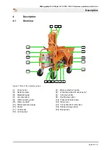
Page 19: ...1 Pump motor 2 Motor protection handle 3 Deflector plate 4 Protective grille with sack opener 5 Material hopper 6 Carrying handle 7 Air compressor 8 Double stop castor 9 Water sampling valve 10 Pressu...

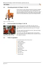
Page 20: ...ure 10 G 4 X Super G 4 X XL The new mixing pump G 4 X with 400V three phase drive was specially developed for pumping spraying and applying dry mortar pasty materials for machine use and much more up...

Page 21: ...reduced To avoid machine breakdowns and excessive wear on pump motor mixing shaft and pump always use orig inal PFT spare parts such as PFT rotors PFT stators PFT mixing shaft PFT mortar hoses These...

Page 22: ...switch has not tripped 6 Main terminal 7 Dummy connector connection for remote control 8 Yellow control lamp no water 9 Red control lamp motor protection switch activated 10 Release the pump reverse...

Page 23: ...h motor 1 Pump motor 6 05 kW or 7 5 kW 2 Rubber mixing tube with adapter flange 3 Pump unit D 6 3 D 6 4 4 5 4 Water manifold 5 1 2 3 4 8 7 6 Figure 14 Water tap assembly 1 Water flow meter 150 1 500l...

Page 24: ...or safety related reasons Some advantages of the mortar pressure gauge Exact adjustment of the correct mortar consistency Constant control of the right conveying pressure Early detection of clogging o...

Page 25: ...e star wheel is running in continuous mode independent from the air control In this position material can be added to the mixing section if the pump is deactivated Figure 19 Selector switch pressure b...

Page 26: ...very hood is used for feeding dry material to the mixing pump PFT G 4 directly from the silo container In case of an empty alarm in the hopper the mixing pump is switched of via the remote control soc...

Page 27: ...air hose DN19 Geka Geka 40 m Item no 20212100 Remote control cable with switch 25 m Item no 20456929 Extension cable 5 x 4 mm RED 5 32 A 25 m 400 V 3 Ph Item no 20423920 You can find further accessor...

Page 28: ...eps according to the instruc tions in this user manual Prior to starting your work ensure that all components are complete and undamaged Prior to starting your work ensure that all covers and protecti...

Page 29: ...table face protection NOTE The machine operator or the person working in the dusty area always has to wear a dust protection mask when filling the machine The rules of the Committee on Dangerous Subst...

Page 30: ...rial at the level sensor 1 the machine switches off 2 Figure 25 Deactivate level sensor The machine can also be operated without a level sensor If the level sensor selector switch 2 is set to the left...

Page 31: ...e has to be stopped to eliminate the defects 5 3 Preparing the machine Prior to operating the machine carry out the following steps for preparing the machine 5 3 1 Risk of injury from running star whe...

Page 32: ...otating parts Improper operation may lead to serious damage to persons or property The respective drive motors must be operated only with the control box of the machine 1 Connect the power supply for...

Page 33: ...only clean water free of solids The minimum pres sure is 2 5 bar when the machine is running Observe the Drinking Water Protection Ordinance in Part 1 NOTE Never let the pump run dry as this reduces t...

Page 34: ...n 2 3 4 Figure 37 Setting the water quantity 1 Press the water supply button 1 to adjust the water quantity 2 At the same time adjust the anticipated amount of water required at the needle valve 2 whi...

Page 35: ...e 39 Preparing the mortar hose 1 Connect the cleaner coupling 1 at the water extraction valve 2 2 Connect the mortar hose 3 to the cleaner coupling 2 3 Open the water sampling valve 2 and water the mo...

Page 36: ...t they do not tear away from their own weight 4 3 Figure 41 Switching on 4 Switch the machine one by pressing the green pushbutton 3 control voltage ON 5 The level sensor is still deactivated switch l...

Page 37: ...stem it switches off using the pressure switch off 5 3 8 Feeding dry material to the machine Figure 45 Bagged goods Loading with bagged goods Depending on the equipment the machine can be fed with bag...

Page 38: ...to be disconnected In case of danger proceed as follows 1 Switch off the main switch immediately 2 Secure the main switch against reactivation 3 Inform responsible person at the operational site 4 If...

Page 39: ...terial to the machine 1 3 2 4 7 5 Figure 49 Switching on the machine 1 Turn the main switch 1 to ON 2 Turn the level sensor selector switch 2 to right position 3 Turn the booster pump selector switch...

Page 40: ...nger of injury from discharged mortar Discharged mortar may lead to injuries to eyes and face Never look into the spray gun Always wear protective goggles Always position yourself in such a way that y...

Page 41: ...rface to be sprayed we recommend application on wall surfaces from top to bottom Uniform mixing and spraying cannot be ensured if the amount of water is insufficient This can clog the hoses and the pu...

Page 42: ...o be observed regarding breaks 1 Figure 55 Closing the air tap 1 Close the air tap 1 if the work is interrupted for a longer period of time 2 Figure 56 Switching off the machine 2 Switch off the machi...

Page 43: ...by pressing the red pushbutton 1 control voltage OFF 2 Turn the main switch 2 to OFF 5 11 Action in case of power failure Figure 59 Turn main switch to the OFF position Turn main switch to the OFF pos...

Page 44: ...rged mortar may lead to injuries to eyes and face Never look into the spray gun Always wear protective goggles Always position yourself in such a way that you are not hit by the mortar being discharge...

Page 45: ...ack switch 7 Switch the machine one by pressing the green pushbutton 6 control voltage ON 8 The machine starts again as soon as the air tap at the spray gun is re opened NOTE In case of a longer power...

Page 46: ...Figure 65 Blowing the water manifold dry 2 Turn the level sensor selector switch 4 to left position 3 Turn the star wheel selector switch 5 to the 0 position 4 Turn the booster pump selector switch 6...

Page 47: ...king with the machine there is the risk that the energy supply is switched on without authorisation This poses a danger to life for the persons in danger area Before starting work switch off all elect...

Page 48: ...trol voltage OFF 5 Switch off the air compressor at the red switch 6 Open air tap on the spray gun WARNING Danger of injury from discharged mortar Discharged mortar may lead to injuries to eyes and fa...

Page 49: ...pray gun 4 Remove fine plaster nozzle 5 from the spray gun 5 Undo eye bolt 6 and pull air nozzle tube 7 out of the spray head 6 Open the water extraction valve until the sponge ball exits the spray gu...

Page 50: ...haft 1 and clean it 5 13 7 1 Inserting the mixing tube cleaner 1 2 Figure 73 Inserting the mixing tube cleaner 1 Take the mixing tube cleaner 1 and cleaning shaft 2 from the tool box Insert the mixing...

Page 51: ...pushbutton 5 control voltage ON 5 Allow the machine to run for approx 5 10 seconds until the mixing tube is cleaned 6 Switch off the machine by pressing the red pushbutton 6 control voltage OFF 7 Turn...

Page 52: ...lt 5 14 1 Safety Personnel The work for rectification of faults described here can be carried out by the operator unless marked otherwise Some works must be carried out only by specially trained skill...

Page 53: ...lt displays The following installation indicates faults Pos Light signal Description 1 Red control lamp Lights up on motor protection switch fault Check the motor protection switch 2 Yellow control la...

Page 54: ...art current Fuse defective Change fuse Service technician Insufficient drop in pressure in the remote control due to blocked air duct or air nozzle pipe Clean blocked air duct or air nozzle pipe Opera...

Page 55: ...Set or replace air pressure safety switch Service technician Compressed air hose or gaskets defective Replace compressed air hose replace gaskets or check compressor Service technician Air tap on spra...

Page 56: ...ervice technician During opera tion water rises in the mixing tube Hose blockage due to mortar being too thick high pressure due to low water factor Remedy hose blockage increase water factor Service...

Page 57: ...G Danger from discharged material Never detach hose couplings if the feed pressure has not been fully released Material to be conveyed can be discharged under pressure and cause injuries particularly...

Page 58: ...yes and face Never look into the spray gun Always wear protective goggles Always position yourself in such a way that you are not hit by the mortar being discharged 1 Undo both nuts 2 on the pressure...

Page 59: ...sition 4 Turn the selector switch star wheel 5 to the AUTO position 5 Switch the machine one by pressing the green pushbutton 6 control voltage ON 6 Let the machine run for a short while without morta...

Page 60: ...evere injuries or considerable property damage Prior to starting the works ensure that there is enough space to carry out the works Ensure order and safety at the assembly site Unat tached components...

Page 61: ...ting WARNING Danger to life from unauthorised restarting When working with the tool there is the risk that the energy supply is switched on without authorisation This poses a danger to life for the pe...

Page 62: ...ean replace filter of compressor Service technician Monthly Clean replace plastic screen in strainer Operator Monthly Clean replace the strainer screen in the pressure reducer Service technician 6 4 M...

Page 63: ...Remove filter cover 4 Take out the filter 5 Blow through the filter from the inside to the outside or tap it 6 Replace the filter in case of heavy contamination 7 Insert the filter with the solid sid...

Page 64: ...t strainer screen and screw on the closure cap Screen for pressure reducer Item no 20156000 6 4 5 Setting value pressure switch water 1 Figure 88 Pressure switch water Pressure switch water 1 Machine...

Page 65: ...lever 1 CAUTION Ensure that the locking lever engages at the mixing tube 2 3 4 Figure 92 Changing the pump 3 Loosen the collar nuts 3 4 Remove pump unit rotor and stator 4 5 Insert new rotor and stat...

Page 66: ...re that all tools materials and other equipment used have been removed from the work area 4 Clean the work area and remove any spilled materials such as liquids processing material or similar 5 Ensure...

Page 67: ...the machine can be found on the Internet at www pft net Open the Document Centre under Service Downloads In this area select the spare parts list category In addition select the machine you are looki...

Page 68: ...efore Prior to starting the works ensure that there is suffi cient space Carefully handle components with sharp edges Ensure order and cleanliness at the working place Loose components and tools on to...

Page 69: ...cable work safety and environmental protection regula tions Prior to starting the disassembly Switch off device and secure against restarting Disconnect the entire energy supply from the machine and d...

Page 70: ...ispose of remaining components sorted according to the type of material NOTE Environmental damage due to incorrect disposal Electrical scrap and components lubricants and other process materials are s...

Page 71: ...Mixing pump G 4 X Super G 4 X XL Part 2 Overview operation and service Disposal page 71 72...

Page 72: ...S AT YOUR SITE Knauf PFT GmbH Co KG Postfach 60 97343 Iphofen Einersheimer Stra e 53 97346 Iphofen Germany Telephone 49 9323 31 760 Fax 49 9323 31 770 Technical hotline 49 9323 31 1818 info pft net ww...

Reviews: