background image


PFT continuous mixer HM 2002 Overview - Operation - Spare parts lists 

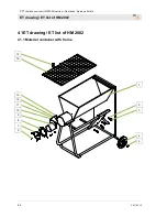
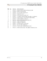
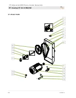
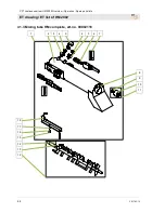
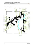
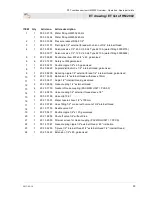
ET drawing / ET list of HM 2002 


2017-03-14


45 


ITEM 

Qty 

Article no. 

Article description


00 00 21 28 

On/Off switch of HM 22/2002, 230 V 50 Hz complete with connection cable 
and thermal protection 14 A  

20 45 69 42  Thermo switch 10-12 A 230 V 50 Hz 

00 05 44 88 

Emergency stop button cover (yellow/red complete with screws) for On-Off 
switch of HM 22/2002 230 V 1Ph. (art. no. 00002128) 

20 20 66 02  Safety nut M5, galvanised 

20 20 64 06  Cylinder head screw M5 x 50, galvanised 

20 54 63 00  Cover hood of HM 2000/2002 RAL 2004 

20 54 66 00  V-belt  

20 20 78 11  Flat head screw M8 x 12, galvanised 

20 54 65 00  V-belt pulley diameter 63 mm  

10 

20 20 78 03  Hex. screw M8 x 80 galvanised 

11 

20 54 62 10  Motor fixing angle of HM 2002 RAL 2004 

12 

20 14 19 00  Motor 2.2 KW 230 V 50 Hz 1 Phase 


00 59 33 73  Motor 2.2 kW 120 V 60 Hz 1 Phase  


On request 

Motor 2.2 KW 230 V 60 Hz 1 Phase 

13 

On request 

Capacitor 130 mF D=46 x 84 (Motor 2.2 KW 230 V 50 Hz 1 Phase) 

14 

00 02 12 00  Capacitor 50 myF D=45 x 116 (Motor 2.2 KW 230 V 50 Hz 1 Phase) 

15 

20 44 81 00  Klixon relay type 2CR4-273 (motor 2.2 KW 230 V 50 Hz 1 Phase) 

16 

20 44 80 00  Resistance 0.68 OHM, 12.5 W (motor 2.2 KW 230 V 50 Hz 1 Phase) 

17 

20 54 77 00  Protective cap for HM 2000/2002 

18 

20 54 67 00  Flange bearing unit complete with pivot ball bearing 

19 

00 03 62 43  Y-flange bearing, type FYTB 25TF 

20 

20 54 74 01  Drive shaft complete with clamping pins and feather keys 245 mm 

21 

20 54 64 00  V-belt pulley diameter 355 mm 


Summary of Contents for HM 2002

Page 1: ...pare parts lists Article number of the operating manual 20 09 98 59 HM 2002 article number 20 54 60 03 HM 2002 with rubber mixing tube article number 00 02 04 73 HM 2002 rubber mixing tube 2 2 KW 120...

Page 2: ...7 03 14 Knauf PFT GmbH Co KG P O Box no 60 97343 Iphofen Einersheimer Stra e 53 97346 Iphofen Germany Tel 49 9323 31 760 Fax 49 93 23 31 770 Technical hotline 49 9323 31 1818 info pft iphofen de www p...

Page 3: ...230 V 50 Hz 13 11 2 Power connection 230 V 60 Hz 14 11 3 Power connection 120 V 60 Hz 14 12 Accessories 15 13 Brief description 16 13 1 CONTINUOUS MIXER PFT HM 2002 16 14 Material 16 14 1 Fields of a...

Page 4: ...onnect power connection 120 V 32 35 4 Secure against restarting 33 35 5 Clean HM 2002 33 35 6 Cleaning the mixing shaft 33 35 7 Cleaning the mixing tube 34 35 8 Clean the material container 34 35 9 Cl...

Page 5: ...ccording to Outdoor Directive 2000 14 EC Internal production control as per article 14 paragraph 2 in connection with annex V This declaration only refers to the machine in the state in which it has b...

Page 6: ...g conditions and the operational requirements as needed however at least once a year by an expert Pressure vessels have to undergo the prescribed expert inspections The inspection results have to be d...

Page 7: ...of the device both parts have to be read and observed Together they form one operating manual 4 Technical data 4 1 General information Dimensions Detail Value Unit Weight Art No 20 54 60 03 125 kg Wei...

Page 8: ...0 Hz 230 V Power consumption max 14 5 A Speed of mixing shaft 280 rpm AC current 230 V 50 Hz 16 A supply 3 x 2 5 mm only to site main cabinet with specified RCCB 30 mA 16 A Fuse protection at least 16...

Page 9: ...nection 3 pin 2P PE supply 3 x 4 mm only to site main cabinet with specified RCCB 30 mA 32 A Fuse protection at least 32A type C 4 6 Operating conditions Environment Detail Value Unit Temperature rang...

Page 10: ...is located on the front side of the material container on the motor side and includes the following information Manufacturer Type Year of manufacture Machine number 9 Quality Control sticker Fig 4 Qu...

Page 11: ...rview of HM 2002 1 2 3 4 5 11 10 9 8 7 6 Fig 5 Overview of HM 2002 1 Rubber mixing tube 2 Water to mixing tube 3 ON OFF switch 4 Protective grille with sack opener 5 Material container with frame 6 Wh...

Page 12: ...case of risk of frost 4 Solenoid valve 5 Pressure reducer 6 Water extraction 7 Water extraction valve 8 Water inlet from water supply or water pump 10 3 Retrofit kit for water flow meter 100 1 000 l h...

Page 13: ...lange 3 Quick closure 4 Water inlet at mixing tube 5 Mixing shaft 6 Rubber mixing tube 10 5 Mixing shaft Fig 9 Mixing shaft 1 Sprocket mixing shaft HM 2002 4 levels article number 00431198 without mor...

Page 14: ...lists Connections 14 2017 03 14 11 2 Power connection 230 V 60 Hz Fig 12 Power connection 230 V 1 Alternating current connection 1 230 V 60 Hz 11 3 Power connection 120 V 60 Hz Fig 13 Power connectio...

Page 15: ...PFT continuous mixer HM 2002 Overview Operation Spare parts lists Accessories 2017 03 14 15 12Accessories Recommended accessory equipment PFT machines and device catalogue or under www pft eu...

Page 16: ...iable easy to use Thanks to the rubber mixing tube there is hardly any caking and the mixer is almost self cleaning 14Material 14 1 Fields of application CONTINUOUS MIXER PFT HM 2002 Mixes all bagged...

Page 17: ...ortable transportation maintenance free square external bearing protected quick closure New PFT rubber mixing tube for all continuous mixers best suitable for processing adhesive mortar no long term c...

Page 18: ...observe the symbols and instruction on the package Use only the specified anchorage points Remove packaging only shortly before the assembly Suspended loads WARNING Danger to life from suspended load...

Page 19: ...t documentation or on the delivery note of the carrier NOTE Report any defect as soon as it is detected Claims for damages can be asserted only within the valid warranty period 16 3 Transport in indiv...

Page 20: ...eparate materials according to type and size and reuse or recycle ATTENTION Environmental damage due to wrong disposal Packaging materials are valuable raw materials and in many cases they can be reus...

Page 21: ...ccident risks Increased noise level may cause permanent hearing deficiencies At close range of the machine 78 dB A can be exceeded due to operational conditions Close range is a distance of less than...

Page 22: ...current The connection line has to be fused properly Connect the machine only to a power source with permissible RCCB 30 mA RCD residual current operated device type A 20 3 Power connection 120 V 60 H...

Page 23: ...ressure reducer 4 Check whether the strainer screen in the pressure reducer 3 is clean Screen for pressure reducer Article number 20156000 5 Screw the brass cup 2 back 21 2 Connecting the water hose 1...

Page 24: ...the expected amount of water at the needle valve 1 1 Close the needle valve 2 Then open the needle valve by two turns 3 In this position the water flow rate is approx 200 ltr h 4 Using the needle valv...

Page 25: ...damage or have other adverse health effects NOTE The machine operator or the person working in the dusty area always have to wear a dust protection mask when filling the machine The rules of the Commi...

Page 26: ...machine at 120 V Fig 29 Switching on at 120 V 1 Switch on the machine using the black switch 1 2 EMERGENCY STOP button 2 Turn the button to the right in the direction of the arrow to loosen the butto...

Page 27: ...xing tube depending on the setting time of the material and the duration of the interruption pay attention to outside temperature The guidelines of the material manufacturers have to be observed regar...

Page 28: ...Recover persons from the danger zone initiate First Aid measures 7 Keep access routes free for emergency vehicles After the rescue operations 8 If the severity of the emergency permits inform the com...

Page 29: ...Depending on the type of fault commission authorised skilled personnel or rectify the fault yourself NOTE The following fault table gives information on who is authorised to rectify the fault 32 2 Fa...

Page 30: ...ial in mixing tube Empty the mixing tube and start again Operator Excessively dry material in mixing tube Empty the mixing tube and start again Operator Water is not flowing Solenoid valve hole in mem...

Page 31: ...hen turn down slowly Operator Mixing shaft defective no original PFT agitator Replace the mixing shaft with original PFT agitator Operator Pressure reducer set incorrectly or defective Adjust or repla...

Page 32: ...be cleaned daily after work 1 Stop filling material into the material container shortly before end of work 2 As soon as diluted material emerges from the mortar outlet switch off the machine by press...

Page 33: ...supplies before starting any work and secure against restarting If protective covers have been removed for cleaning purposes they must be properly put back again without fail after completion 35 5 Cle...

Page 34: ...he mixing shaft 3 Slightly lubricate the bearing journal 2 of the mixing shaft after cleaning 35 7 Cleaning the mixing tube 1 Fig 41 Cleaning the mixing tube 1 Open the quick closures 1 on both sides...

Page 35: ...ctive grille and secure it 35 10 Setting the mixing shaft 2 1 Fig 44 Setting the mixing shaft 1 Assemble clean and dry parts only 2 Keep the quick closures at the mixing tube clean 3 Move the cleaned...

Page 36: ...t by the operator unless marked otherwise Some maintenance work must only be carried out by specially trained technical personnel or exclusively by the manufacturer Work on the electrical system must...

Page 37: ...e 1 Electrical system DANGER Danger of death from electric current There is danger to life if you come in contact with electrical components Activated electrical components can carry out uncontrolled...

Page 38: ...strainer screen in water inlet Operator 38Maintenance work 38 1 Strainer screen Fig 48 Strainer screen in water inlet Check the strainer screen in water inlet daily 1 Remove the strainer screen 1 from...

Page 39: ...he dosing shaft at the lubricating nipple 1 once in six months Implementation by operator 38 3 Changing the V belt Fig 51 V belt 1 Loosen the four screws 1 and remove the cover hood 2 2 Loosen the cou...

Page 40: ...has to be dismantled and disposed of in an environmental friendly manner 39 1 Safety Personnel Disassembly must be carried out only by specially trained technical personnel Work on the electrical syst...

Page 41: ...e against restarting Physically separate the complete energy supply to the device discharge stored residual power Remove operating supplies as well as remaining processing materials and dispose of in...

Page 42: ...ntinuous mixer HM 2002 Overview Operation Spare parts lists ET drawing ET list of HM 2002 42 2017 03 14 41ET drawing ET list of HM 2002 41 1 Material container with frame 1 2 3 4 5 15 14 13 12 11 10 9...

Page 43: ...cap 20s x N 2 7 6 4 20 20 96 11 Countersunk screw with hexagon socket M4 x 12 galvanised 7 1 20 54 95 15 Clamping flange for mixing tube gasket HM2 200 2002 8 1 20 54 80 10 Rubber gasket D154 x D107...

Page 44: ...PFT continuous mixer HM 2002 Overview Operation Spare parts lists ET drawing ET list of HM 2002 44 2017 03 14 41 2 Gear motor 1 2 3 4 5 6 7 8 9 10 11 12 13 14 21 20 19 18 17 16 15...

Page 45: ...5 00 V belt pulley diameter 63 mm 10 1 20 20 78 03 Hex screw M8 x 80 galvanised 11 1 20 54 62 10 Motor fixing angle of HM 2002 RAL 2004 12 1 20 14 19 00 Motor 2 2 KW 230 V 50 Hz 1 Phase 1 00 59 33 73...

Page 46: ...T continuous mixer HM 2002 Overview Operation Spare parts lists ET drawing ET list of HM 2002 46 2017 03 14 41 3 Mixing tube HM complete art no 00002116 1 2 3 4 5 4 3 6 7 8 9 10 11 18 17 16 15 14 13 1...

Page 47: ...locking device 7 2 20 20 85 22 Splint bolt with washer und splint galvanised 8 2 20 20 99 92 Threaded pin with hexagon socket M6 x 6 galvanised 9 1 20 02 60 01 Plain bearing flange sleeve 10 1 20 02...

Page 48: ...2002 Overview Operation Spare parts lists ET drawing ET list of HM 2002 48 2017 03 14 41 4 Mixing tube HM rubber art no 00012594 1 2 3 4 5 6 7 8 9 10 11 12 13 33 34 32 31 30 29 28 27 26 25 24 23 22 2...

Page 49: ...14 1 00 00 25 69 Dosing shaft HM 22 24 35l at 280 rpm 15 1 20 54 76 06 Clamping pin 10 x 50 16 1 20 54 76 05 Clamping pin 6 x 50 17 1 00 43 11 98 Sprocket mixing shaft HM 2002 4 levels RAL2004 18 1 00...

Page 50: ...PFT continuous mixer HM 2002 Overview Operation Spare parts lists ET drawing ET list of HM 2002 50 2017 03 14 41 5 Cable set 120 V 60 Hz art no 00593375 1 2 3...

Page 51: ...ration Spare parts lists ET drawing ET list of HM 2002 2017 03 14 51 ITEM Qty Article no Article description 1 1 On request CEE connection plug 3 x 16 A yellow 2 1 On request Motor protection switch 3...

Page 52: ...uous mixer HM 2002 Overview Operation Spare parts lists ET drawing ET list of HM 2002 52 2017 03 14 41 6 Water fitting HM 2002 1 2 3 4 5 6 7 8 10 19 9 10 11 12 13 14 15 16 5 15 17 18 5 6 24 23 22 13 2...

Page 53: ...52 00 Reducing nipple 1 2 external thread 1 4 internal thread galvanised 10 2 20 21 53 03 Ball valve 1 4 external thread with sleeve 10mm 11 1 20 20 36 11 Angle 1 2 internal thread galvanised 12 2 20...

Page 54: ...FT continuous mixer HM 2002 Overview Operation Spare parts lists ET drawing ET list of HM 2002 54 2017 03 14 41 7 Retrofit kit for water flow meter 100 1 000 l h for HM 2002 1 2 3 4 5 6 7 8 9 10 11 12...

Page 55: ...meter HM 2002 5 1 20203511 Bend 1 2 90 external thread external thread galvanised 6 1 20200900 Geka coupling 1 2 external thread PACKING UNIT 10 PCS 7 1 00002213 Water flow meter 100 1000 l h 250 mm...

Page 56: ...ion value of water 8 Connections 13 CONTINUOUS MIXER PFT HM 2002 16 D Danger to life from rotating parts 22 Dimension sheet HM 2002 10 Disassembly 41 Disassembly 40 Disconnect power supply 28 Disposal...

Page 57: ...he machine into operation 26 Q Quality Control sticker 10 R Reaction in the event of faults 29 Remove connection cable 37 Retrofit kit for water flow meter 100 1 000 l h for HM 2002 12 54 Risk of fros...

Page 58: ...PFT continuous mixer HM 2002 Overview Operation Spare parts lists 58 2017 03 14...

Page 59: ...PFT continuous mixer HM 2002 Overview Operation Spare parts lists 2017 03 14 59...

Page 60: ...e parts lists 60 2017 03 14 THE FLOW OF PRODUCTIVITY Knauf PFT GmbH Co KG P O Box no 60 97343 Iphofen Einersheimer Stra e 53 97346 Iphofen Germany Phone 49 9323 31 760 Fax 49 9323 31 770 Technical hot...

Reviews: