background image


PFT Air Compressor LK

 402 IV 

Overview – Operation – Spare

 Parts Lists 


Page 30 


28.01.2019


7  Solution 

Malfunction 

Cause 

Correction 

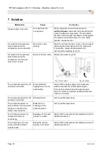
Pressure drop in the tank.


Air outlet from the 
connections.


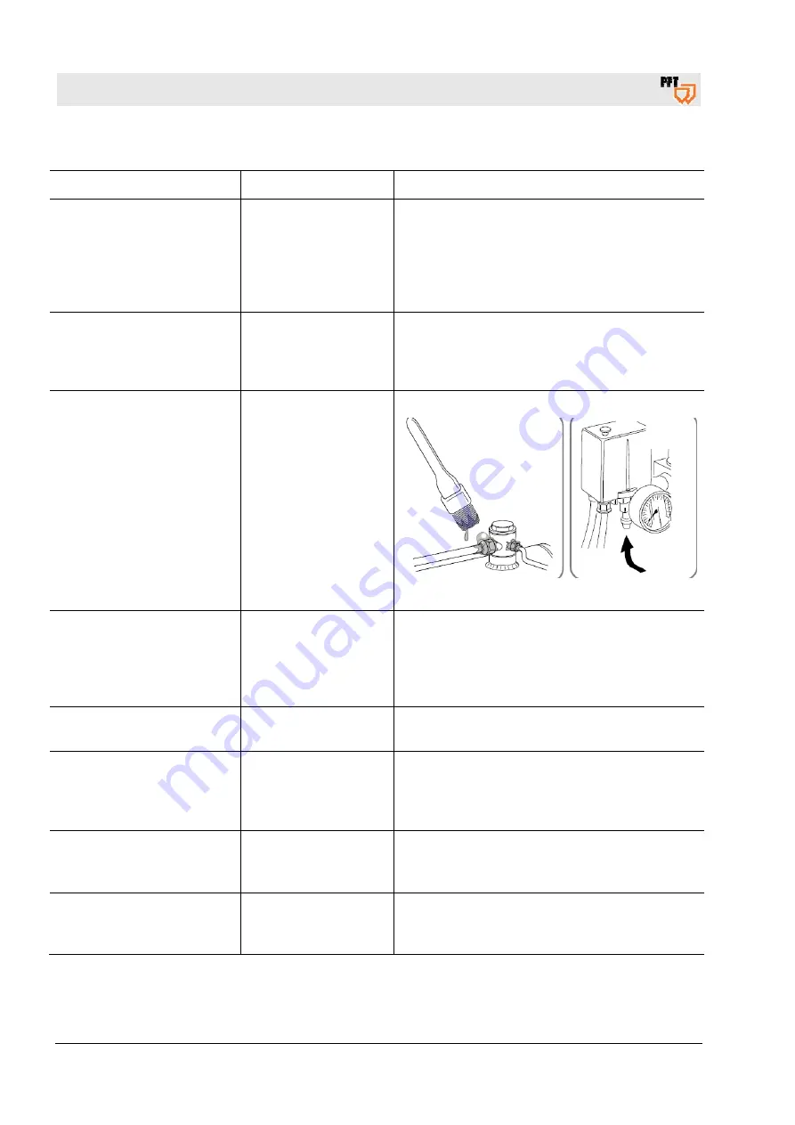
Bring compressor to maximum pressure, 

switch off power

 and brush all connections with 

a brush soaked in soapy water. The air outlets 
become visible through air bubbles. Firmly tighten 
the relevant connections (Fig. 19). If air outlet 
persists, request service.


Air outlet from the pressure 
switch valve when the 
compressor is at a standstill. 

Non-return valve 
leaking. 

Drain the air from the tank, remove the non-return 
valve plug and thoroughly clean the valve seat. 
If necessary, replace sealing element D 
and reinstall everything (Fig. 18). 

Air outlet from the pressure 
switch valve when the 
compressor is running for 
more than 1 minute. 

Break of the idle valve. 

Replace the valve (Fig. 20). 


Fig. 19: Air outlet


Fig. 20: Valve


The compressor switches off 
and does not restart. 

Motor protection 
tripping due to motor 
overheating. 

Switch off the power supply via the pressure 
switch and press the restart button (Fig.8). 
If the motor protection should respond again 
when the motor is restarted, qualified personnel 
must be consulted. 

The compressor switches off 
and does not restart. 

Winding blown. 

Call in qualified personnel. 

The compressor does not 
switch off when the maximum 
pressure is reached; the 
safety valve responds. 

Malfunction or 
breakage of the 
pressure switch. 

Call in qualified personnel. 

The compressor does not 
charge and heats up 
excessively. 

Breakage of the head 
gasket or a valve. 

Switch off the compressor immediately and call in 
qualified personnel. 

The compressor runs very 
loudly and with rhythmic, 
metallic beats. 

Eating the bronze 
bearing or the bush. 

Switch off the compressor immediately and call in 
qualified personnel. 


Summary of Contents for LK 402 IV

Page 1: ...ng Manual PFT Air Compressor LK 402 IV Safety Overview Operation Spare Parts Lists Item number of operating manual 00 25 52 64 Item number of the machine parts list 00 23 31 74 Read the operating manu...

Page 2: ...28 01 2019 Knauf PFT GmbH Co KG Postfach 60 97343 Iphofen Einersheimer Stra e 53 97346 Iphofen Germany Tel 49 0 93 23 31 760 Fax 49 0 93 23 31 770 Technical hotline 49 9323 31 1818 info pft net www p...

Page 3: ...ts 17 2 8 Signs 17 3 Operation 20 3 1 Preliminary remark 20 3 2 Description 21 3 3 Proposed scope of application 21 4 General safety standards 21 4 1 What to do 22 4 2 What to refrain from 22 4 3 Remo...

Page 4: ...ines for the equipment must be followed at all times Read the manual carefully before starting any work It is an integral part of the product and must be kept near the machine and accessible to operat...

Page 5: ...t will lead to death or serious injury if it is not avoided WARNING Indicates a potentially dangerous situation that can lead to death or serious injury if it is not avoided CAUTION Indicates a potent...

Page 6: ...ons in this manual have been compiled according to the currently valid norms and instructions up to date technology and our many years of experience in the branch The manufacturer accepts no liability...

Page 7: ...urer Violation of these terms can lead to claims for compensation We reserve all other further rights 1 6 Spare parts WARNING Danger of injury due to incorrect spare parts Incorrect or defective spare...

Page 8: ...from the individual working conditions on the operating site of the device These additional dangers must be summarised as operational instructions for the correct use of the equipment During the enti...

Page 9: ...l training knowledge and experience as well as knowledge of the relevant regulations in a position to carry out the work assigned to him and to recognise possible dangers independently qualified elect...

Page 10: ...s unauthorised individuals are found within the work area 2 2 3 Inspection The compressor must be inspected by a specialist once a year The test must be documented This inspection must be carried out...

Page 11: ...rom the material manufacturer Adhere to all specifications in this operating manual to the letter In particular do not use the device for the following purposes They are not considered as intended Do...

Page 12: ...ing is tight fitting rips easily if caught has narrow sleeves and has no protruding parts It is primarily intended as protection from being caught by moving machine parts Do not wear rings chains and...

Page 13: ...rous situations Electric current DANGER Danger of death due to electric current Contact with live components can lead to death or serious injury Damage to electrical insulation or individual component...

Page 14: ...ou cannot be hit should mortar escape Noise WARNING Danger of damage to hearing The loud noises associated with the work area can cause serious damage to hearing Therefore Always wear ear protection w...

Page 15: ...time Before opening covers ensure that parts are no longer moving Wear close fitting protective clothing in the danger zone Dirt and objects lying around CAUTION Risk of tripping due to dirt and obsta...

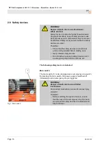
Page 16: ...d before starting work Never disable safety devices Do not obstruct access to safety devices such as emergency stop buttons ripcords etc The following safety device is installed 1 Fig 1 Main switch Ma...

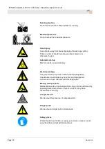
Page 17: ...gency stop immediately Initiate first aid measures Rescue people from the danger zone Inform supervisors at the site Alert doctor and or fire brigade Clear access roads for rescue vehicles 2 8 Signs T...

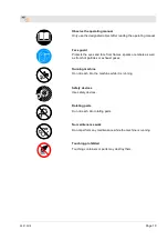
Page 18: ...ically Electrical voltage Only electricians may work in areas with this designation Unauthorised individuals may not enter such designated work areas or open cabinets with this designation Moving mach...

Page 19: ...es sparks or embers as well as from hot particles or exhaust gases Running machine Do not reach into the machine while it is running Safety devices Use safety devices Rotating parts Do not reach into...

Page 20: ...If the manual is lost please request a copy Customer service and spare parts service Only use original spare parts for servicing the compressor Non original spare parts involve risks that may cause p...

Page 21: ...ressor to more than 50 of its capacity and not to keep it in continuous operation for more than 15 minutes 3 3 Proposed scope of application Fig 2 Main switch The compressor must not be exposed to moi...

Page 22: ...sor it is recommended to use sound insulation measures 4 2 What to refrain from Do not work in closed rooms or near open flames Do not touch the cylinder head cooling fins or pressure hose as these pa...

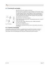
Page 23: ...done by two persons Machine with tank over 50 litres capacity Using protective gloves and scissors cut the strapping and pull the carton off the top of the machine Lift the compressor using a lifting...

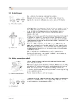
Page 24: ...please observe the measures and recommendations listed below Fit the wheels and anti vibration protection Fig 3 remove the plug from the compressor head and fit the intake filter if it is not already...

Page 25: ...but always switch the switch on the pressure switch to the OFF position Fig 7 This allows the compressed air contained in the head to be discharged and facilitates subsequent switching on The correct...

Page 26: ...nt damage to the pressure reducer 6 Maintenance 6 1 Note NOTE In order to keep the compressor in perfect condition at all times some periodic maintenance is required Before carrying out any maintenanc...

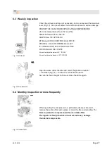
Page 27: ...Dacnis P100 FUCHX Renolin 104L VG100 At room temperature below 5C ISO 68 At room temperature above 25 C ISO 150 Fig 14 Condensate Open the valve under the tank and under the pressure reducer if insta...

Page 28: ...instructions Oil pollutes the environment For disposal contact the responsible authority 6 6 Cleaning Fig 17 Cleaning Clean all ribbed parts of the compressor This keeps the cooling system efficient a...

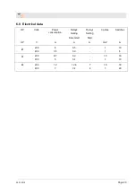
Page 29: ...rical data HP Volts Power consumption Relays Setting Direct start Relays Setting Start Cables Switches HP V A A A mm A 2 230 400 6 3 5 6 5 3 9 1 1 10 6 3 230 400 8 7 5 9 2 5 4 1 5 1 16 10 4 230 400 12...

Page 30: ...han 1 minute Break of the idle valve Replace the valve Fig 20 Fig 19 Air outlet Fig 20 Valve The compressor switches off and does not restart Motor protection tripping due to motor overheating Switch...

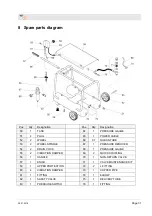
Page 31: ...UBE 53 2 WHEEL SPINDLE 67 1 PRESSURE REDUCER 54 2 DRAIN COCK 68 1 PRESSURE GAUGE 55 2 VIBRATION DAMPER 69 2 QUICK COUPLING 56 1 HANDLE 70 1 NON RETURN VALVE 57 1 KNOB 71 1 VALVE MAINTENANCE KIT 59 1 U...

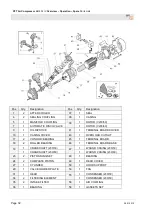
Page 32: ...ARD COVER 10 1 CASING COVER 43 1 OVERLOAD CUTOUT 17 2 CON ROD BEARING 45 1 TERMINAL BOARD 18 2 ROLLER BEARING 46 1 TERMINAL BOARD BASE 19 1 CRANKSHAFT 230 50 47 1 WOUND CASING 230 50 1 CRANKSHAFT 230...

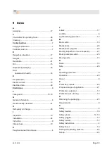
Page 33: ...nstallation 24 Instruction 9 Intended use 10 K Keep the manual for later use 4 L Labels 17 Liability 6 Light breathing protection 12 M Main switch 16 Maintenance 26 Maintenance program 28 Monthly insp...

Page 34: ...Page 34 28 01 2019 Signs 17 Solution 30 Spare parts 7 Spare parts diagram 31 Specialists 9 Start up 24 Switching on 25 Symbols in the danger zone 17 Symbols in the manual 5 U Unauthorised individuals...

Page 35: ...28 01 2019 Page 35...

Page 36: ...re Parts Lists Page 36 28 01 2019 PFT THE FLOW OF PRODUCTIVITY Knauf PFT GmbH Co KG Postfach 60 97343 Iphofen Einersheimer Stra e 53 97346 Iphofen Germany Tel 49 9323 31 760 Fax 49 9323 31 770 Technic...

Reviews: