background image


Part 2 EC Declaration of Conformity Overview – Operation 

Applying mortar 


2020-03-25


39 


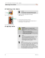
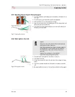
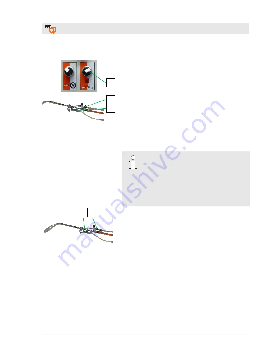
43.1 Opening the air tap on the spray gun 


Fig.66: Switching on 


Fig.67: Opening the air valve 

1.  Turn the selector switch Pump motor directions of rotation (1) to 

the right. 

2.  Point the spray gun toward the wall to be plastered. 

3.  Check that no-one is in the spray gun range.  

4.  Open the air valve (2) on the spray gun and the compressor will 

start (with pressure switch-off). 

5.  The machine starts automatically as soon as the handle (3) at 

the spry gun is pressed. 


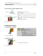
43.2 Interruption of work 


NOTE! 

Generally, the setting times of the materials to be 
processed must be observed: 

Clean the equipment and hoses as appropriate for 
the setting time of the material and the length of 
the interruption (take outdoor temperature into 
account). 

Observe the guidelines of the material 
manufacturer regarding interruptions. 


Fig.68: Closing the air valve 

1.  For brief work interruptions, close the air valve (1). 

2.  The machine stops. 

3.  Close the air valve (2) when the nozzle on the sprayer is freely 

blown 

4.  The air compressor switches off (must be on pressure switch-

off) 

5.  By opening the air valve (1), the machine will start running again. 


Summary of Contents for RITMO L FC-230V plus

Page 1: ...MO L FC 230V plus powercoat 1 Ph 50 Hz 2 2 kW Item number of the parts list machine 00659659 RITMO L FC 230V plus powercoat 1 Ph 50 Hz 2 2 kW Item number of the parts list machine 00659661 RITMO L FC...

Page 2: ...2020 03 25 Knauf PFT GmbH Co KG Postfach 60 97343 Iphofen Einersheimer Stra e 53 97346 Iphofen Germany Tel 49 9323 31 760 Fax 49 9323 31 770 Technical hotline 49 9323 31 1818 info pft net www pft net...

Page 3: ...Gear motor 13 13 3 Chassis with compressor and control box 14 14 Description of assemblies 14 14 1 Overview of control box RITMO L plus powercoat 14 14 2 Overview of water manifold RITMO L plus 15 15...

Page 4: ...ne 34 38 Putting the machine into operation 35 38 1 Checking the mortar consistency 35 38 2 Switching on the RITMO L plus powercoat with material 35 39 Potentiometer 35 40 Mortar hoses 36 40 1 Prepari...

Page 5: ...Cleaning the mortar hose 54 55 5 Coupling the water hose 55 55 6 Clean mixing tube 55 55 7 Inserting the mixing tube cleaner 56 55 8 Cleaning the mixing tube RITMO 56 55 9 Cleaning the material hoppe...

Page 6: ...tive 2000 14 EC Internal manufacturing inspection as per Article 14 Section 2 in conjunction with Appendix V This declaration applies only to the machine in the condition it was in when sold Component...

Page 7: ...anual This manual provides important information and instructions on the correct use of the equipment Adherence to all defined safety and handling instructions is a prerequisite for a safe working env...

Page 8: ...on Spare part lists 8 2020 03 25 4 Spare part lists You can find spare part lists for the machine in the Internet under www pft net 4 1 Accessories 3 For recommended accessories equipment see PFT Mach...

Page 9: ...Test The machine is EMC tested and meets the strict requirements of protection class B The switch cabinet is equipped with a mains filter Specification Value Unit Voltage AC current 50 Hz 230 V Max cu...

Page 10: ...rating period 8 hours 5 5 Connection values for water Fig 1 Water connection Specification Value Unit Operating pressure min 2 5 bar Connection 1 2 inches 6 Sound power level Guaranteed sound power le...

Page 11: ...late contains the following information Manufacturer Type Year built Machine number Permissible operating pressure 11 Quality control sticker Fig 4 Quality control sticker The quality control sticker...

Page 12: ...ate 4 Push handle 5 Water supply to mixing tube rubber mixing zone 6 Wheel 7 Compressed air from air compressor to spray gun 8 Water inlet water connection from water supply 9 Rubber mixing zone 10 Re...

Page 13: ...old 13 Assembles RITMO L plus 13 1 Gear motor with material hopper and pump unit Fig 7 Material hopper assembly The mixing pump PFT RTIMO L plus powercoat comprises the following main components Gear...

Page 14: ...or frequency converter 2 Potentiometer for motor speed material volume 3 Selector switch Vibrator ON OFF 4 Connection for air compressor COMP R 80 230V socket blue continuous current 5 Connector for v...

Page 15: ...Water to mixing tube 5 Shut off valve water outlet 6 Water outlet for cleaning the mortar pressure hose 7 Antifreeze water drain cock 8 Needle valve for water quantity 9 Primary water pressure gauge...

Page 16: ...d locking other functions 16 2 Water selector switch Fig 15 Water selection switch The RITMO can be used for two application areas Selection switch latching The machine is operated without water Use a...

Page 17: ...Double wrench 16x18 Art No 00262402 20x22 Art No 00099111 Sponge ball 17 mm fixed Art No 00010411 Control box key double bit 5 mm Art No 20444500 Reamer with toolholder Art No 00021219 Cleaning brush...

Page 18: ...se of fitting block 18 1 Purpose of fitting block The equipment has been designed and constructed only for the intended use described below Application range Primary use for water and neutral non adhe...

Page 19: ...all processing guidelines from the material manufacturer Strictly observe all instructions in this operating manual We accept nor esponsibility for damages caused by i mpr oper or unauthorised us e Th...

Page 20: ...ically ensured from a water tank by the PFT pressure booster pump for the constant water supply to the PFT machine engineering The flow pressure of min 2 5 bar when the machine is running is ensured o...

Page 21: ...ble 21 Initial operation filling the pump Fig 26 Filling the pump Before putting the PFT High Pressure Pump into operation for the first time fill the pump with water so that the air in the pump housi...

Page 22: ...se as possible to the water supply point pressing is better than sucking When all these points have been observed the pump can be switched on Depending on the length of the suction hose priming may ta...

Page 23: ...g on requirements The machine should generally be started up at maximum speed to avoid malfunctions The dry material is mixed with water and blended in the mixing zone The water flow rate is adjusted...

Page 24: ...ible with one another and form a single constructive unit together with the machine Failure to follow these recommendations will result not only in the voiding of the warranty but the quality of the m...

Page 25: ...e assembly Suspended loads WARNING Danger of death due to suspended loads Falling or swinging parts can pose a fatal hazard when heavy loads are lifted Therefore Never step underneath suspended loads...

Page 26: ...accept it only under reservations Note the damage on the transportation documents or the delivery note of the carrier Submit the appropriate claim NOTE Always submit a claim for the defects as soon as...

Page 27: ...e 1 Carry out the following steps before transporting 2 First unplug the main power cable 3 Detach all other connected cables 4 Remove the water supply lines 5 Begin transport 6 Remove loose parts dur...

Page 28: ...RNING Danger of injury due to improper operation Improper operation can lead to serious injuries or equipment damage Therefore Carry out all operating steps as described this operating manual Before s...

Page 29: ...efore operating the machine carry out the following work steps as preparation Fig 35 Protective grille DANGER Rotating mixing shaft Reaching into the material hopper poses a risk of injury The protect...

Page 30: ...2 Pull connector plug of the air compressor 2 off the control box 3 Selector switch 3 at the middle position 30 2 Motor connecting cable for pump motor Fig 38 Motor connection cable WARNING Danger of...

Page 31: ...nning Observe the Drinking Water Protection Ordinance in Part 1 NOTE Never allow the pump unit to run dry since this will significantly shorten its service life 5 Remove nozzle 4 from rubber mixing tu...

Page 32: ...ater flow button 1 Fig 46 Presetting 2 At the same time adjust the expected water quantity at the needle valve 2 3 Water flow visible at the sight glass 3 of the water flow meter and at the position o...

Page 33: ...tar pressure gauge Fig 48 Mortar pressure gauge DANGER Operating pressure too high Machine components can fly open in an uncontrolled manner and injure the operator Do not operate the machine without...

Page 34: ...L plus SET item number 00619834 comprising Dust collector class M Supplementary set for dust collector M Dust collecting hood attachment RITMO L plus complete RAL9002 Without item 1 36 Filling the ma...

Page 35: ...me to position 10 readjust as required 3 Dummy plug 3 must be connected to the remote control socket 4 Turn selector switch 4 Pump motor directions of rotation to the right machine starts 5 Check mate...

Page 36: ...e injuries Hoses that tear off can lash wildly and injure those standing nearby 40 2 Connecting the mortar hose 1 2 Fig 58 Connecting the mortar hose 1 Connect the mortar hose 1 to the mortar pressure...

Page 37: ...1 4 5 Fig 61 Spray gun 1 Connect compressed air hose 1 to the spray gun 2 2 Make sure that the air valve 3 on the spray gun is closed 3 Connect mortar hose 4 to the spray gun 2 4 Connect remote contr...

Page 38: ...injuries to the eyes and face Never look into the spray gun Always wear protective goggles Always position the machine so that you cannot be hit should mortar escape NOTE The maximum pumping distance...

Page 39: ...the handle 3 at the spry gun is pressed 43 2 Interruption of work NOTE Generally the setting times of the materials to be processed must be observed Clean the equipment and hoses as appropriate for th...

Page 40: ...the machine at the pump motor selector switch 3 position 0 6 Switch off the air compressor 44 Working with pastes 44 1 Mortar pressure gauge Fig 71 Mortar pressure gauge DANGER Operating pressure too...

Page 41: ...essurized check mortar pressure gauge Mixing material could escape under pressure and cause serious injury especially to the eyes Torn off hoses can knock around and injure bystanders 45 2 Connect mor...

Page 42: ...e 1 to air fitting NOTE An air compressor must be connected to the air fitting DANGER Never undo hose couplings while the compressed air hose is pressurised 47 2 Connecting the spray gun 2 3 1 4 5 Fig...

Page 43: ...tion without water to the right Turn potentiometer 2 for motor speed material quantity to position 10 readjust as required Turn selector switch 3 rotation pump motor to the right 48 Applying material...

Page 44: ...e but will fall back to the normal working pressure of 12 15 bar after a short running time 48 1 Opening the air valve on the spray gun Fig 81 Opening the air valve 1 Point the spray gun toward the wa...

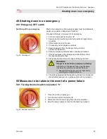
Page 45: ...y vehicles have unobstructed access 7 If the seriousness of the emergency warrants this inform the responsible authorities 8 Assign specialist personnel to begin rectifying the fault WARNING Danger of...

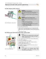
Page 46: ...tar pressure gauge 1 to see if the pressure has fallen to 0 bar If necessary discharge any mortar pressure by unscrewing the screws 2 slightly and cover the working area with foil 3 Tighten screws 2 a...

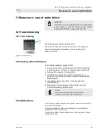
Page 47: ...ons which present a risk of material damage or personal injury perform an emergency stop immediately 2 Determine the cause of the malfunction 3 If troubleshooting requires working in the danger zone s...

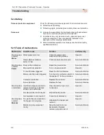
Page 48: ...ssure booster pump Service technician Machine does not start Power Power cable is defective Repair the power cable Service technician Main switch not activated Turn on the main switch Operator FI circ...

Page 49: ...r a short period Dirt trap screen is dirty Clean or replace the screen Operator Pressure reducer filter dirty Clean or replace the screen Operator Hose connection or water line too small Enlarge the h...

Page 50: ...e pressure flange Service technician Part not original PFT spare part Use an original PFT spare part Service technician Water level rises in mixing tube during operation Backpressure in mortar hose hi...

Page 51: ...out 54 Clearing hose blockages Fig 87 Switching off DANGER Danger due to escaping material Never detach hose couplings if the feed pressure has not been fully released The conveyed material can escape...

Page 52: ...efore Always wear protective goggles Protective clothing protective gloves safety shoes ear protection Always position the machine so that you cannot be hit should mortar escape 1 Undo both screws 2 o...

Page 53: ...unit 9 Switch on air compresso 10 Turn the pump motor 2 and vibrator 1 selector switch to the right open the air valve on the spray gun and operate the handle as described in section 42 1 55 End of s...

Page 54: ...ure on the machine When opening machine components these can fly open in an uncontrolled manner and injure the operator Only open the machine if the pressure has fallen to 0 bar NOTE The mortar hoses...

Page 55: ...5 5 Coupling the water hose Fig 95 Water hose 1 Couple water hose 1 to the mixing tube 55 6 Clean mixing tube 2 4 Fig 96 Opening the motor tilt flange NOTE There must not be any more material in the m...

Page 56: ...motor tilt flange 1 with gear motor 2 Close quick fastener 2 3 Insert 10 pole connector plug 3 4 Turn the main switch 4 to the I position 5 Turn potentiometer 5 for motor speed material volume to pos...

Page 57: ...s those in the danger area at extreme risk Therefore Before starting work switch off the electrical power supply and secure it against being switched back on again Interrupt the power supply by removi...

Page 58: ...er and clean it 5 Push the cleaned rubber mixing zone 2 back in the material hopper 6 Refasten the suction flange 4 with nuts 56 4 Complementing the remixer with a pump unit Fig 104 Remixer pump unit...

Page 59: ...steps when the pump is not operating and there is a danger of frost Fig 106 Disconnecting the water supply 1 Remove the water hose 1 from the water inlet 2 Remove water hose 2 from the water nozzle a...

Page 60: ...air compressor 3 Keep the water flow button 2 pressed for approx 10 seconds 4 The water is blown out of the manifold with compressed air 5 Open all water valves and blow out with compressed air again...

Page 61: ...le Electrical system Fig 111 Removing the connection cable DANGER Danger of death due to electric current Contact with live components can lead to death or serious injury Live electrical components ca...

Page 62: ...se wear can be identified during regular inspections reduce the required maintenance intervals as appropriate for the actual signs of wear For questions regarding maintenance tasks and intervals conta...

Page 63: ...Remove dirt trap screen 2 and clean every two weeks 3 Replace the dirt trap screen if dirt is severe 4 Insert dirt trap screen and screw in sealing screw Dirt trap screen for pressure reducer Item num...

Page 64: ...n environmentally sound manner after reaching the end of its useful life 61 1 Safety Personnel Disassembly may only be performed by specially trained personnel Work on electrical systems may only be c...

Page 65: ...again Disconnect the entire energy supply from the machine and discharge the residual energy Remove operating and auxiliary materials as well as residual processing materials and dispose of them in a...

Page 66: ...upply 37 Connect mortar hose 41 Connecting the air hose 37 Connecting the air hose 42 Connecting the mortar hose 36 Connecting the spray gun 37 Connecting the spray gun 42 Connection to power distribu...

Page 67: ...Mortar pressure gauge 24 Mortar pressure gauge 40 Motor connecting cable for pump motor 30 O Opening the air tap on the spray gun 39 Opening the air valve on the spray gun 44 Operating manual 7 Operat...

Page 68: ...L plus powercoat 12 Switching off in an emergency 45 Switching off RITMO Powercoat 58 Switching off the energy supplies 53 Switching on RITMO L plus 32 Switching on the air compressor 37 Switching on...

Page 69: ...Part 2 EC Declaration of Conformity Overview Operation Notes 2020 03 25 69 64 Notes...

Page 70: ...Part 2 EC Declaration of Conformity Overview Operation 70 2020 03 25...

Page 71: ...Part 2 EC Declaration of Conformity Overview Operation 2020 03 25 71...

Page 72: ...w Operation 72 2020 03 25 PFT THE FLOW OF PRODUCTIVITY Knauf PFT GmbH Co KG Postfach 60 97343 Iphofen Einersheimer Stra e 53 97346 Iphofen Germany Tel 49 9323 31 760 Fax 49 9323 31 770 Technical hotli...

Reviews: