background image


Mixing pump RITMO L plus FC-230V Overview – Operation 

Mortar hoses 


2020-11-09


39 


43 Mortar hoses 

43.1 Preparing the mortar hoses 


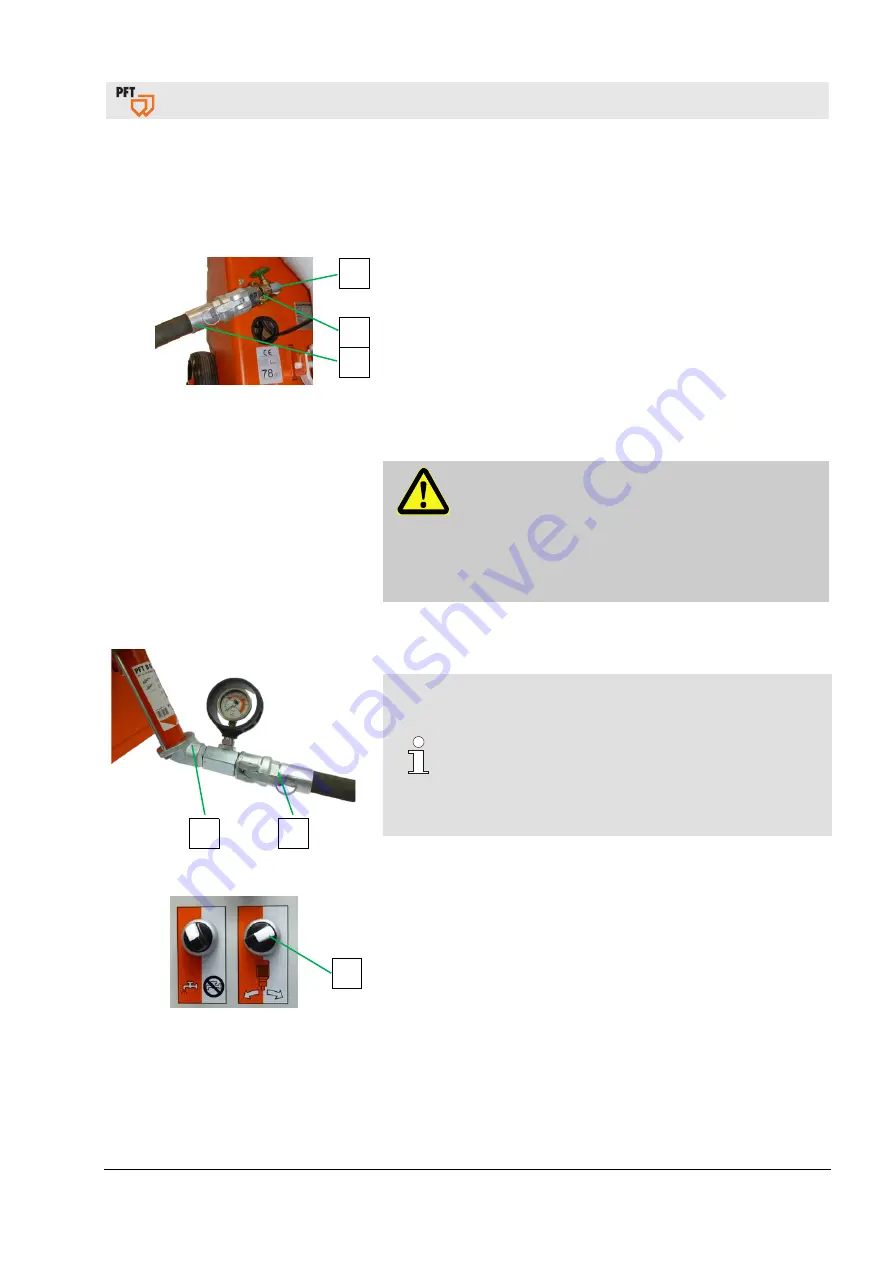
Fig. 71: Preparing the mortar hose 

1.  Connect the cleaner coupling (1) to the shut-off valve (2). 
2.  Connect the mortar hose (3) to the cleaner coupling (1). 
3.  Open shut-off valve (2) and flush mortar hose (3) with water. 
4.  Remove the mortar hose and cleaner coupling again 

and disconnect from one another. 

5.  Completely empty the mortar hose of water. 
6.  Prime the mortar hose by wetting it with about 1 litre of 

wallpaper paste. 

7.  The wallpaper paste is pumped through the mortar hose 

with the first mixture. 


DANGER! 

Never detach hose couplings if the mortar hoses 

are under pressure (check mortar pressure gauge). 

Mixed material can escape under pressure and 

lead to serious injuries, especially eye injuries. 
Hoses that tear off can lash wildly and injure those 

standing nearby! 


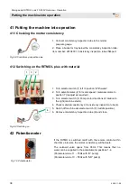
43.2 Connecting the mortar hose 


Fig. 72: Connecting the mortar hose 

1.  Connect the mortar hose (1) to the mortar pressure gauge (2). 


NOTE! 

Make sure the couplings are clean and connected 

properly, and do not leak. Dirty couplings and 

rubber seals are leaky and allow water under 

pressure to escape, which inevitably leads to 

blockages. 
Carefully secure risers so that they do not 

tear away from their own weight. 

2.  Lay mortar hoses with a radius large enough so that the hoses 

do not kink. 


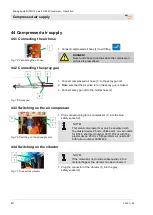
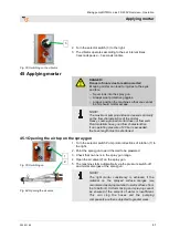
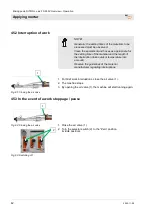
Fig. 73: Switching on


3.  Turn the selector switch Pump motor directions of rotation (3) to 

the right. 

4.  Allow the machine to run until all the wallpaper paste 

has emerged from the end of the mortar hose. 

5.  Collect the wallpaper paste with a suitable container 

and dispose of it according to regulations. 

6.  Switch off machine at selector switch (3) (middle position). 


Summary of Contents for RITMO L plus

Page 1: ...Contents 2020 11 09 Operating manual Mixing pump RITMO L plus FC 230V Overview Operation Item number of operating manual 00627846 Read the operating manual prior to beginning any work...

Page 2: ...2 1 Ph 50 Hz 2 2 kW without compressor without accessories 00659513 RITMO L FC 230V plus SD 6 3 soft 1 Ph 50 Hz 2 2 kW with accessories 00662714 RITMO L FC 230V plus SD 6 3 soft 1 Ph 50 Hz 2 2 kW wit...

Page 3: ...r RITMO L plus 14 14 Assembles RITMO L plus 14 14 1 Gear motor with material hopper and pump unit 14 14 2 Gear motor 14 14 3 Chassis with compressor and control box 15 15 Description of assemblies 15...

Page 4: ...5 34 1 Putting RITMO L plus into operation 35 34 2 Presetting the water flow rate 35 34 3 Watering the mixing zone 36 35 Mortar pressure gauge 36 36 Hazardous dust 36 37 DUSTCATCHER RITMO L plus SET 3...

Page 5: ...Cleaning the mortar hose 54 54 5 Coupling the water hose 55 54 6 Clean mixing tube 55 54 7 Inserting the mixing tube cleaner 56 54 8 Cleaning the mixing tube RITMO 56 54 9 Placing the machine on its r...

Page 6: ...4 EC Internal manufacturing inspection as per Article 14 Section 2 in conjunction with Appendix V This declaration applies only to the machine in the condition it was in when sold Components attached...

Page 7: ...environment Additionally the on site accident prevention regulations and general safety guidelines for the equipment must be followed at all times Read the manual carefully before starting any work I...

Page 8: ...s comprised of two booklets Part 1 Safety General safety instructions for mixing pumps conveying pumps Item number 00172709 Part 2 Overview operation servicing and spare part lists this booklet Both p...

Page 9: ...L plus 133 kg Length with pump 915 mm Width 600 mm Overall height 1450 mm Individual weights Specification Value Unit Chassis Frame 64 2 kg Motor with tilt flange 30 kg Material hopper 18 kg Hopper d...

Page 10: ...m Recommended value depending on conveying height condition and version of pump mortar quality composition and consistency 6 4 Output values RITMO L plus SD6 3 Pump output SD6 3 Specification Value Un...

Page 11: ...ion Value Unit Maximum continuous operating period 8 hours 6 8 Connection values for water Fig 1 Water connection Specification Value Unit Operating pressure min 2 5 bar Connection 1 2 inches 7 Sound...

Page 12: ...ate contains the following information Manufacturer Type Year built Machine number Permissible operating pressure 12 Quality control sticker Fig 4 Quality control sticker The quality control sticker c...

Page 13: ...te 4 Push handle 5 Water supply to mixing tube rubber mixing zone 6 Wheel 7 Compressed air from air compressor to spray gun 8 Water inlet water connection from water supply 9 rubber mixing zone 10 Pre...

Page 14: ...ld 14 Assembles RITMO L plus 14 1 Gear motor with material hopper and pump unit Fig 7 Material hopper assembly The mixing pump PFT RTIMO L plus comprises the following main components Gear motor with...

Page 15: ...ght glass for frequency converter 2 Potentiometer for motor speed material volume 3 Selector switch Vibrator ON OFF 4 Selector switch Pump 5 Selector switch Operation with water as mixing pump without...

Page 16: ...e compressor ON OFF 8 Pressure control connection 9 Air pressure switch switches the machine ON OFF 15 3 Overview of water manifold RITMO L plus 1 2 3 4 5 6 Fig 13 Water manifold 1 Pressure reducer 2...

Page 17: ...f Selector switch latching The machine starts up when the main switch is switched on Selector switch left spring return The pump motor goes into reverse thereby relieving the pump and locking other fu...

Page 18: ...No 20210500 Mandrel 4 0 mm diameter Art No 00073670 Control box key double bit 5 mm Art No 20444500 Dirt trap screen for Geka coupling 10 items Art No 20152000 Fig 20 Mixing tube cleaner RITMO L PLUS...

Page 19: ...5 m without support Art No 00001795 Fig 27 Rotor remover complete Art No 00401188 Fig 28 Support for remote control switch 2 x D 36 Art No 20190221 Fig 29 Assembling spray for PFT rotor stator 100 ml...

Page 20: ...1101 RONDO 25 mm 5 m hydraulic Art No 00021103 Fig 35 Air hose DN9 Ewo V part Ewo M part 16 m Art No 00008521 Air hose DN9 Ewo V part Ewo M part 5 m Art No 00077240 Fig 36 Water hose air hose DN12 Gek...

Page 21: ...itial after pressure 1 bar Maximum media and ambient temperature 75 C Installation position unimportant preferably horizontal 20 2 Purpose of solenoid valve Application range Solenoid valves for liqui...

Page 22: ...ded use of air compressor 21 1 Purpose of air compressor The equipment has been designed and constructed only for the intended use described below Caution The air compressor is only intended for gener...

Page 23: ...responds to the national and international safety regulations and can therefore also be used in damp rooms or in the open air Areas with as clean and dry air as possible should be preferred Make sure...

Page 24: ...cally ensured from a water tank by the PFT pressure booster pump for the constant water supply to the PFT machine engineering The flow pressure of min 2 5 bar when the machine is running is ensured on...

Page 25: ...e 24 Initial operation filling the pump Fig 41 Filling the pump Before putting the PFT High Pressure Pump into operation for the first time fill the pump with water so that the air in the pump housing...

Page 26: ...mp is still not delivering after a short time this may have one of the following causes There is still air in the pump and this has to be completely vented again The suction line is not air tight and...

Page 27: ...stators PFT mixing shafts PFT material hoses These components are compatible with one another and form a single constructive unit together with the machine Failure to follow these recommendations will...

Page 28: ...assembly Suspended loads WARNING Danger of death due to suspended loads Falling or swinging parts can pose a fatal hazard when heavy loads are lifted Therefore Never step underneath suspended loads F...

Page 29: ...cept it only under reservations Note the damage on the transportation documents or the delivery note of the carrier Submit the appropriate claim NOTE Always submit a claim for the defects as soon as t...

Page 30: ...1 Carry out the following steps before transporting 2 First unplug the main power cable 3 Detach all other connected cables 4 Remove the water supply lines 5 Begin transport 6 Remove loose parts duri...

Page 31: ...NING Danger of injury due to improper operation Improper operation can lead to serious injuries or equipment damage Therefore Carry out all operating steps as described this operating manual Before st...

Page 32: ...fore operating the machine carry out the following work steps as preparation Fig 50 Protective grille DANGER Rotating mixing shaft Reaching into the material hopper poses a risk of injury The protecti...

Page 33: ...s 2 Pull connector plug of the air compressor 2 off the control box 3 Selector switch 3 at the middle position 33 2 Motor connecting cable for pump motor Fig 53 Motor connection cable WARNING Danger o...

Page 34: ...ning Observe the Drinking Water Protection Ordinance in Part 1 NOTE Never allow the pump unit to run dry since this will significantly shorten its service life 5 Remove nozzle 4 from rubber mixing tub...

Page 35: ...Open needle valve 2 by two turns to the left 5 Press the water flow button 3 Fig 51 until no more air bubbles can be seen in the water flowmeter 4 6 Adjust the expected water volume at the needle val...

Page 36: ...open in an uncontrolled manner and injure the operator Do not operate the machine without the mortar pressure gauge Only use mortar hoses with a permissible operating pressure of at least 40 bar The...

Page 37: ...L plus SET item number 00619834 comprising Dust collector class M Supplementary set for dust collector M Dust collecting hood attachment RITMO L plus complete RAL9002 Without item 1 39 Filling the mat...

Page 38: ...sition With water 2 Turn potentiometer 2 for motor speed material volume to position 7 readjust as required 3 Turn selector switch 3 Pump motor directions of rotation to the right machine starts 4 Che...

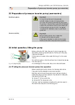
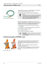
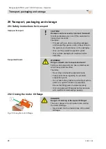
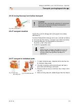
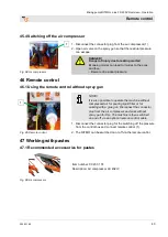
Page 39: ...lead to serious injuries especially eye injuries Hoses that tear off can lash wildly and injure those standing nearby 43 2 Connecting the mortar hose 2 1 Fig 72 Connecting the mortar hose 1 Connect t...

Page 40: ...Connect spray gun 2 to the mortar hose 4 44 3 Switching on the air compressor Fig 76 Switching on the air compressor 1 Plug connector plug for air compressor 1 into the blue safety socket 2 NOTE This...

Page 41: ...erials have good flow characteristics If an operating pressure of 20 bar is exceeded the hose length must be shortened 45 1 Opening the air tap on the spray gun Fig 79 Switching on Fig 80 Opening the...

Page 42: ...f the interruption take outdoor temperature into account Observe the guidelines of the material manufacturer regarding interruptions 1 Fig 81 Closing the air valve 1 For brief work interruptions close...

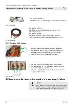
Page 43: ...out spray gun Fig 85 Remote control NOTE It is also possible to operate the machine without compressed air for pouring liquid filler or for working with a glue gun Disconnect the connector plug from t...

Page 44: ...tes Fig 89 Blind cap 1 Disconnect the connector plug from the air compressor 2 Uncouple water hose 1 from the mixing tube add close both water inlets on the mixing tube with blind cap 2 3 The paste ca...

Page 45: ...ure emergency vehicles have unobstructed access 7 If the seriousness of the emergency warrants this inform the responsible authorities 8 Assign specialist personnel to begin rectifying the fault WARNI...

Page 46: ...n 2 Check the mortar pressure gauge 1 to see if the pressure has fallen to 0 bar If necessary discharge any mortar pressure by unscrewing the screws 2 slightly 3 Tighten screws 2 again 50 3 Switching...

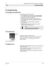
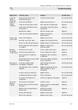
Page 47: ...e regarding the malfunction 5 Depending on the malfunction either rectify it yourself or have authorised specialists do so NOTE A table below lists particular malfunctions and who is authorised to han...

Page 48: ...sure booster pump Service technician Machine does not start Power Power cable is defective Repair the power cable Service technician Main switch not activated Turn on the main switch Operator FI circu...

Page 49: ...a short period Dirt trap screen is dirty Clean or replace the screen Operator Pressure reducer filter dirty Clean or replace the screen Operator Hose connection or water line too small Enlarge the hos...

Page 50: ...pressure flange Service technician Part not original PFT spare part Use an original PFT spare part Service technician Water level rises in mixing tube during operation Backpressure in mortar hose high...

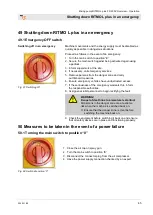
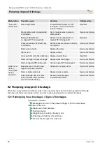
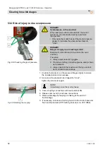
Page 51: ...ut 53 Clearing hose blockages Fig 96 Switching off DANGER Danger due to escaping material Never detach hose couplings if the feed pressure has not been fully released The conveyed material can escape...

Page 52: ...ore Always wear protective goggles Protective clothing protective gloves safety shoes ear protection Always position the machine so that you cannot be hit should mortar escape 1 Undo both screws 2 on...

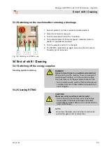
Page 53: ...d 54 End of shift Cleaning 54 1 Switching off the energy supplies Securing against restarting DANGER Danger of death due to unauthorised restarting When working on the machine there is a danger of una...

Page 54: ...re on the machine When opening machine components these can fly open in an uncontrolled manner and injure the operator Only open the machine if the pressure has fallen to 0 bar NOTE The mortar hoses a...

Page 55: ...ose down spray gun with water jet 10 Knock free air nozzle tube 7 with mandrel 11 Switch on compressor and blow air nozzle tube free 12 Reassemble spray gun 54 5 Coupling the water hose Fig 104 Water...

Page 56: ...e coupling claw 4 54 8 Cleaning the mixing tube RITMO Fig 108 Cleaning RITMO 1 Close motor tilt flange 1 with gear motor 2 Close quick fastener 2 3 Insert 10 pole connector plug 3 4 Turn the main swit...

Page 57: ...110 Removing the pump unit 1 Uncouple water hose 1 from the mixing tube 2 Undo screw 2 3 Remove pump unit 3 with mortar pressure gauge and clean Fig 111 Cleaning the rubber mixing zone 4 Pull rubber...

Page 58: ...Danger of death due to unauthorised restarting When working on the machine there is a danger of unauthorised switching on of the electrical supply This puts those in the danger area at extreme risk T...

Page 59: ...n if there is a risk of frost CAUTION Damage due to frost Water that expands on freezing inside the component can cause serious damage Therefore Carry out the following steps when the pump is not oper...

Page 60: ...Connect air hose with Geka coupling and EWO coupling to the compressed air flange 1 and to the water connection 2 57 2 Blowing the water manifold RITMO L plus dry Fig 122 Blowing the water manifold d...

Page 61: ...eep the assembly area clean and tidy Unattached components or tools left lying around or stacked on one another can cause accidents If components have been previously removed ensure that they are moun...

Page 62: ...cal regulations Collect used oil in suitable containers and dispose of it according to the applicable local regulations 58 4 Maintenance plan The next sections describe the maintenance tasks required...

Page 63: ...creen for Geka coupling Item number 20152000 Performed by operator 59 1 1 Dirt trap screen Fig 125 Dirt trap screen 1 Unscrew sealing screw 1 of the pressure reducing valve 2 Remove dirt trap screen 2...

Page 64: ...Pressure switch Pressure switch Compressor 1 Compressor switches ON Compressor switches OFF Compressor 1 1 bar 1 4 bar Pressure switch Plastering machine 2 Machine switches ON Machine switches OFF Pla...

Page 65: ...air compression high temperatures are created at the compressor Protect against contact with hot surfaces or shield the area of traffic or attach warning notices If no pre filter is mounted the compr...

Page 66: ...ing with dry compressed air 59 6 After performing maintenance 1 After maintenance has been completed carry out the following steps before switching on again 2 Check that all previously loosened screw...

Page 67: ...ries Therefore Ensure there is adequate space before starting any work Exercise caution when working with open sharp edged components Keep the work area clean and tidy Components and tools that are st...

Page 68: ...ual processing materials and dispose of them in an environmentally sound manner 61 Disposal Provided no return or disposal agreements have been made recycle the disassembled parts Metallic parts are s...

Page 69: ...osing the snap lock before transport 29 Compressed air supply 40 Compressor DT4 8 11 Connecting the air hose 40 Connecting the mortar hose 39 Connecting the spray gun 40 Connection to power distributo...

Page 70: ...ting manual 7 Operating modes 17 Operating requirements 11 Operation 31 Output values RITMO L plus B4 2wf 10 Output values RITMO L plus SD6 3 10 Output values RITMO L plus SD6 3 soft 10 Overview of ai...

Page 71: ...n emergency 45 Switching off RITMO L plus 59 Switching off the air compressor 43 Switching off the energy supplies 53 Switching on RITMO L plus 35 Switching on the air compressor 40 Switching on the m...

Page 72: ...ew Operation 72 2020 11 09 PFT ALWAYS AT YOUR SITE Knauf PFT GmbH Co KG Postfach 60 97343 Iphofen Einersheimer Stra e 53 97346 Iphofen Germany Tel 49 9323 31 760 Fax 49 9323 31 770 Technical hotline 4...

Reviews: