background image


Mixing pump RITMO XL 400V Overview – Operation 

Feeding machine with factory dry material 


2019-12-11


29 


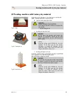
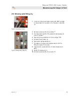
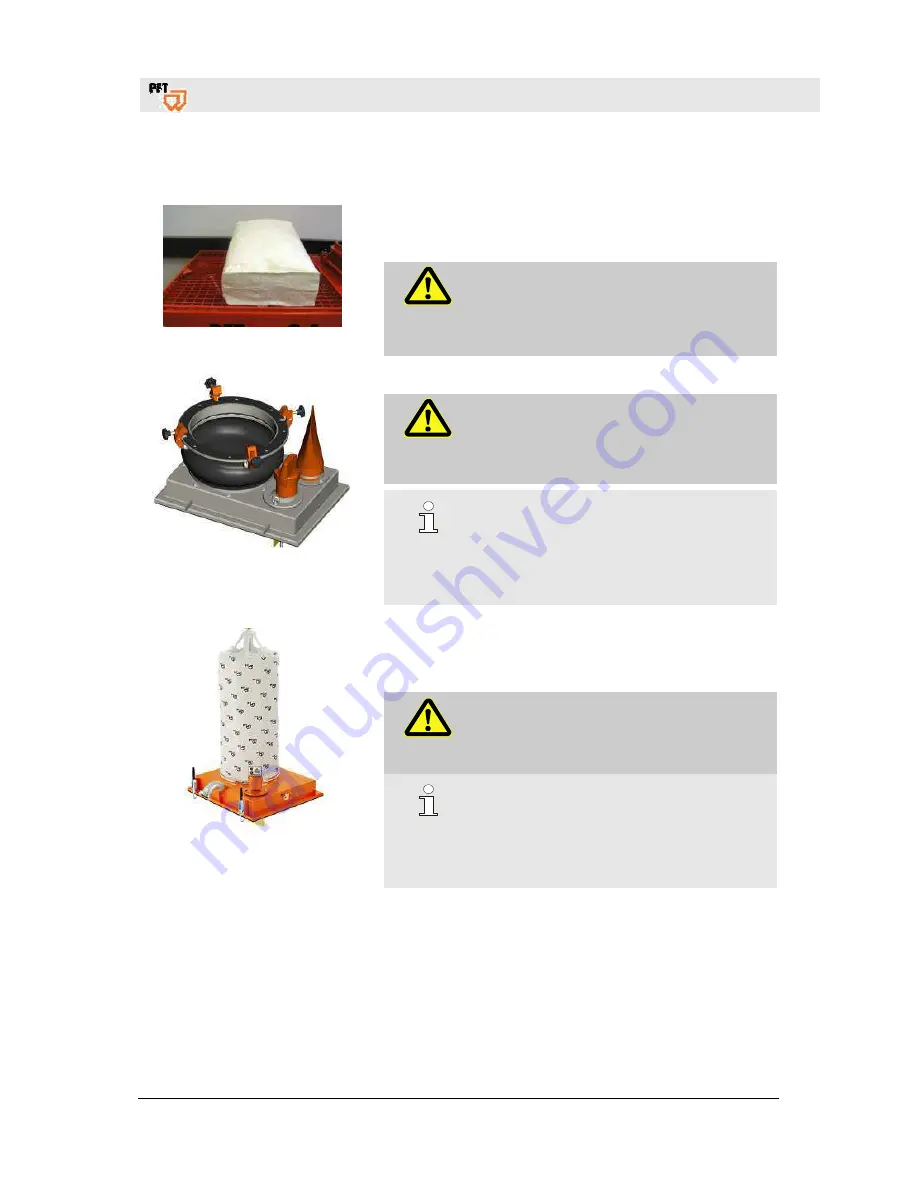
22 Feeding machine with factory dry material 


Fig. 43: Sack 

Depending on the equipment, the machine can be fed with 
sacks, with transfer hood or injection hood. 


Feeding with sacked materials: 


DANGER! 
Danger of injury at sack splitter! 
Sharp edges give rise to danger of injury at the 
sack splitter. 
–  Wear safety gloves. 


Fig. 44: Transfer hood 


Feeding with transfer hood: 


DANGER! 
Do  not  open  the  transfer  hood  when  the 
machine  is  in  operation.  Switch  off  the  main 
reverse  switch  before  opening,  and  disconnect 
power supply. 


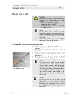
NOTE: 

Feed  the  mixing  pump  RITMO  XL  only  with 
material.  To  do  this,  pull  out  the  dummy 
connector  or  switch  off  machine  via  air 
pressure  control.  Start  work  only  when  the 
filling level indicator shows Full. 


Fig. 45: Injection hood 


Feeding with injection hood: 

Install the injection hood on the adapter injection hood RITMO 
XL complete Art. No. 00201619 (accessory). 
Ensure that the connection is tight. 


DANGER! 

Do  not  open  the  machine  during  compressed 
air  delivery.  Switch  off  the  main  switch  before 
opening, and disconnect power supply. 


NOTE: 

Feed  the  mixing  pump  RITMO  XL  only  with 
material.  To  do  this,  pull  out  the  dummy 
connector  or  switch  off  machine  via  air 
pressure  control.  Start  work  only  when  the 
filling level indicator shows Full. 
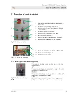


Summary of Contents for RITMO XL 400V

Page 1: ...Operating Instructions Mixing pump RITMO XL 400V Overview Operation Article number of operating instructions 00 23 51 99 Article number of parts list machine 00 18 64 78 Please read the operating inst...

Page 2: ...9 12 11 Knauf PFT GmbH Co KG Postfach 60 97343 Iphofen Einersheimer Stra e 53 97346 Iphofen Germany Tel 49 0 93 23 31 760 Fax 49 0 0 93 23 31 770 Technical hotline 49 9323 31 1818 info pft net www pft...

Page 3: ...remixer for RITMO XL 16 8 2 Covers 16 8 3 Power cable water air hose 16 9 Brief description 17 10 Material 17 10 1 Flowability conveying property 17 11 Mortar pressure manometer 17 12 Safety rules 18...

Page 4: ...40 28 No delivery plunger 43 28 1 Overcoming hose blockers indication of blockages 43 28 2 This can be caused by 43 28 3 Pre existing damage in mortar hose 43 28 4 Changing the direction of rotation o...

Page 5: ...or Directive 2000 14 EG Internal production control as per article 14 paragraph 2 in connection with annex V This declaration only refers to the machine in the state in which it has been placed on the...

Page 6: ...vicinity of the device so that it can be accessed easily by the personnel If the device is handed over to a third party please hand over the operating instructions document too The figures in this op...

Page 7: ...are part lists 2019 12 11 7 3 Spare part lists You can find spare part lists for the machine in the Internet under www pft net 3 1 Accessories 1 2 3 For recommended accessories equipment see PFT Machi...

Page 8: ...er and pump complete 94 kg Weight of undercarriage with pressure boosting pump and compressor 105 kg Weight of control cabinet 21 kg Hopper mass Data Value Unit Filling level 910 mm Hopper content 70...

Page 9: ...r intake maximum 7 kW Fuse Min 3 x 25 A Pump motor drive 5 5 kW Approx pump motor speed 400 rpm Pump motor current intake 11 A Air compressor LK 250 0 9 kW Pressure boosting pump 0 5 kW 3 5 Operating...

Page 10: ...Operating pressure max 30 bar Grain size max 3 mm Pumping width max at 25 mm 30 m Pumping width max at 35 mm 50 m Compressor capacity 0 250 Nm min Pressure boosting pump 25 l min Standard value depend...

Page 11: ...type plate contains the following information Manufacturer Type Year of manufacture Machine number Permissible operating pressure 3 11 Quality control sticker Fig 5 Quality control sticker The qualit...

Page 12: ...or 3 Handle 4 Plastic side lining 5 Wheel with steel rim 6 Water removal valve 7 Compressed air from air compressor to spraying gun 8 Water inlet water connection from water supply line 9 Water inlet...

Page 13: ...et Fig 7 Rear side section view 5 Module description 5 1 Mixing tube with material container The mixing pump PFT RTIMO XL consists of the following main components Fig 8 Material container module Mixi...

Page 14: ...carriage with control cabinet 6 Connections 6 1 Connections of water and air Fig 10 Connection water and air 1 Water extraction 1 2 Connection of air to spraying device 2 3 Connection of water from su...

Page 15: ...tor fault 7 Yellow control lamp Change director of rotation 8 Selector switch Release pump reverse flow 9 Connection for main current 400V 3 Phase 32 A 10 Connection for air compressor 11 Transfer hoo...

Page 16: ...QUIRL Complete ROTOQUIRL II with 35x coupling Article No 20 11 84 00 Remixer for better inclusion and mixing of the material Direct drive through the pin of the rotor Content approx 4 2 l Uniform cons...

Page 17: ...ming materials colors etc have good flow properties The material hose lengths must be shortened if the operating pressure exceeds 30 bar To avoid machine faults increased wear and tear of the pump mot...

Page 18: ...d instructions on the package Use only the provided lifting positions Remove the packages only just before installation Floating loads WARNING Danger to life from floating loads While lifting loads fa...

Page 19: ...ansport documents or on the delivery receipt of the transport agency NOTE Complain about each defect as soon as it is detected Damage claims can be filed only within the valid complaint periods 13 3 T...

Page 20: ...the following conditions Crane and lifting devices must be designed to support the weight of the packages The operator must be authorized to operate the crane Remove all loose parts 1 in the machine T...

Page 21: ...e with the expected transport conditions Environment friendly materials were used for packaging The packaging should protect the individual components from transport damages corrosion and other damage...

Page 22: ...ion can lead to serious personal injuries and material damages Hence All operating steps are to be performed in accordance with the specifications of this operating instructions document Ensure before...

Page 23: ...Place the machine securely on an even surface and lock it against inadvertent movements Do not tilt or move the machine Set the machine up in such a way that it cannot be affected by falling objects T...

Page 24: ...f the water supply line 7 Connect water hose and water inlet 3 8 Remove water hose 4 from mixing tube NOTE Use clean water free of solids only The minimum pressure when the machine is running is 2 5 b...

Page 25: ...glow 3 If the yellow control lamp 2 Change direction of rotation 2 goes off see Faults table 17 1 Default of water flow volume Fig 33 Default 1 Turn the selector switch of the pressure boosting pump...

Page 26: ...Machine components can bounce uncontrollably and injure the operator Do not operate the machine without a mortar pressure manometer Use only mortar hoses with an approved operating pressure of min 40...

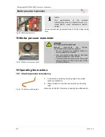
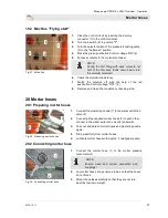
Page 27: ...button Control voltage OFF 4 8 Remove and clean the consistency checking tube 20 Mortar hoses 20 1 Preparing mortar hoses Fig 38 Preparing mortar hoses 1 Connect the plastering nozzle 1 to the water e...

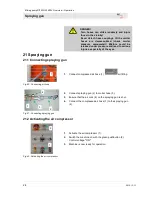
Page 28: ...es 21 Spraying gun 21 1 Connecting spraying gun Fig 40 Connecting air hose 1 Connect compressed air hose 1 air fitting Fig 41 Connecting spraying gun 2 Connect spraying gun 2 to mortar hose 3 3 Ensure...

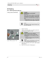
Page 29: ...efore opening and disconnect power supply NOTE Feed the mixing pump RITMO XL only with material To do this pull out the dummy connector or switch off machine via air pressure control Start work only w...

Page 30: ...l to be plastered 2 Ensure that there are no persons in the discharge area of the mortar 3 Open air cock 1 on the spraying gun The machine starts automatically and the mortar is released from the spra...

Page 31: ...ushbutton 2 Control voltage OFF 3 Switch off compressor 3 4 Open the air cock 1 on the spraying gun so that the residual pressure can be released 23 3 Work interruption NOTE In general observe the set...

Page 32: ...lock them against reactivation NOTE The machine must be cleaned daily after work and after long pauses Fig 49 Mortar pressure on 0 bar 1 Switch off machine 2 Check on the mortar pressure manometer wh...

Page 33: ...peration if there is thick dirt accumulation 8 For different hose diameters the mortar hoses must be cleaned separately with the corresponding sponge balls 9 Flush spraying gun with water jet 10 Impac...

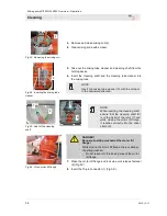
Page 34: ...the scraper in the downward direction Fig 55 Seat of the cleaning shaft NOTE While inserting the cleaning shaft ensure that the cleaning shaft 6 is in the head of the rotor 7 and while closing the mo...

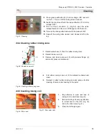
Page 35: ...leaning rubber mixing zone Fig 58 Remove pump unit 1 Detach water hose 1 from the rubber mixing zone 2 Detach the two nuts 2 3 Remove and clean pump unit 3 with pressure flange 4 and mortar pressure m...

Page 36: ...form the following steps if the machine is out of operation due to the danger of frost Fig 62 Disconnect water supply 1 Remove hose 1 from water connecting piece on the rubber mixing zone 2 Remove wat...

Page 37: ...ter fitting dry 2 Set main reverse switch 3 to position I 3 Turn the selector switch of the pressure boosting pump 4 to the 0 position 4 Press the green pushbutton 5 Control voltage ON 5 Activate air...

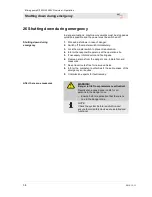
Page 38: ...rsons at the operation site 5 If necessary inform doctor and fire brigade 6 Rescue persons from the danger zone initiate first aid measures 7 Keep travel routes free for rescue vehicles 8 Inform the c...

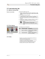
Page 39: ...e type of the fault rectify it yourself or commission an authorized technician to do the job NOTE The faults table given below provides information about who is authorized to rectify faults 27 2 Fault...

Page 40: ...pump Service mechanic Machine does not run power Power supply not OK Repair power supply cable Service mechanic Master switch not activated Activate master switch Operator FI circuit breaker was trig...

Page 41: ...tops after a short duration Dirt trapping sieve is clogged Clean or replace sieve Operator Pressure reducer sieve has dirt deposits Clean or replace sieve Operator Hose connection or water pipe is too...

Page 42: ...p Service mechanic Inner wall of mortar hose is defective Replace mortar hose Operator Rotor is too deep in the pressure flange Replace pressure flange Service mechanic Not original PFT spare parts Us...

Page 43: ...sure flange Marked tapering at couplings Kink in mortar hose Difficult to pump and not properly mixed materials 28 3 Pre existing damage in mortar hose NOTE During a machine fault if the pressure in t...

Page 44: ...rtar hose area with film 28 5 Releasing residual pressure Fig 71 Loosening nuts 1 Loosen the nuts of the tie rod 4 slightly so that possibly existing residual pressure can escape fully 2 Detach hose c...

Page 45: ...n pressure flange 5 or remixer ROTOMIX or ROTOQUIRL 7 Clean mixing zone and mixing coil with water and scraper 8 Reassemble pump fully 30 Measures during water failure NOTE The strainer Article No 001...

Page 46: ...lements and screw torques Electrical system DANGER Danger to life from electric current Contact with electrically live components poses danger to life Activated electrical components can execute uncon...

Page 47: ...aintenance schedule The following sections describe the maintenance jobs that are necessary for optimum and hassle free operation If increased wear and tear is detected during the regular checks short...

Page 48: ...e in the water inlet Check dirt trapping sieve in the water inlet daily 1 Take out dirt trapping sieve from the Geka coupling 2 Clean dirt trapping sieve 3 Replace sieve if there are thick dirt deposi...

Page 49: ...valve 1 9 bar at maximum through flow Needle valve 3 fully wired 31 7 Checking pressure switch Fig 80 Pressure switch The pressure switches must be replaced if the frequency of faults increases The pr...

Page 50: ...a fully closed air pipe 31 8 Measures after maintenance After completion of maintenance jobs perform the following steps before activation 1 Check to ensure that all the loosened screw connections ar...

Page 51: ...nt free space before starting work Handle open sharp edged components carefully Pay attention to cleanliness and order at the workplace Components and tools lying loosely on each other or lying scatte...

Page 52: ...ning processing materials and dispose of them in an environment friendly manner 32 3 Disposal Recycle the dismantled components if no return or disposal agreement was signed Scrap metals Recycle plast...

Page 53: ...ump driver Protective grid Is the protective grid still even Undercarriage Check all welded seams Undercarriage Check that all screw connections have stable seats Undercarriage Check for delay Stabili...

Page 54: ...of rotation 43 Dirt trapping sieve 48 Dismantling 51 52 Disposal 52 Division 6 Emergency stop switch Position 15 Emergency stop 38 Expert testing 53 Fault displays 39 Faults table 40 Feeding machine...

Page 55: ...ts 7 Spraying gun 28 Storage 18 Technical data 8 Transport 18 Transport in single parts 19 Transport inspection 19 Transportation with crane 20 Type plate 11 Undercarriage with compressor and control...

Page 56: ...ndex 56 2019 12 11 PFT THE FLOW OF PRODUCTIVITY Knauf PFT GmbH Co KG Postfach 60 97343 Iphofen Einersheimer Stra e 53 97346 Iphofen Germany Telephone 49 9323 31 760 Telefax 49 9323 31 770 Technical ho...

Reviews: