background image


Mixing Pump RITMO XL FU 230/400 reversible Overview – Operation 

Pumping stopped / blockage 


50 


2019-05-13


43 Pumping stopped / blockage 

When the conveyed material remains stuck in the conveying hoses and cannot be pumped out through 
the hose end, this is a blockage, which can occur in conveying hoses for a number of reasons. 

43.1 Remedying hose blockages / Signs of blockages 

Execution by operator: 

  Blockages can occur in the pressure flange or in the 

mortar hoses. 

  Indications of this are: 

  Sharply increasing delivery pressure, 

  Blocking of pump, 

  Stiffness or blocking of pump motor, 

  Expanding and turning of mortar hose, 

  No material discharge at hose end. 

43.2 This can be caused by: 

  Fully worn out mortar hoses, 

  Job interruption 

  Badly lubricated mortar hoses, 

  Residual water in mortar hose, 

  Clogging of pressure flange, 

  Marked tapering at couplings, 

  Kink in mortar hose, 

  Difficult to pump and not properly mixed materials. 

43.3 Pre-existing damage in mortar hose 


NOTE: 

During  a  machine  fault,  if  the  pressure  in  the  mortar  hose 
exceeds  60  bar  even  for  a  short  duration  due  to  clogging, 
the mortar hose should be replaced, as the hose could be 
damaged  internally  such  that  the  damage  is  not  visible 
externally.


44  Clearing hose blockages 


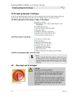
Fig. 73: Switching off


DANGER! 
Danger due to escaping material! 

Never detach hose couplings if the feed pressure has not 
been fully released! The conveyed material can escape 
under pressure and lead to serious injuries, especially 
eye injuries. 

In accordance with the accident prevention regulations of 
the Builder’s Guild, all personnel clearing blockages should 
wear personal safety equipment (safety goggles, protective 
gloves) and position themselves so as not to be hit by 
escaping material. Other persons are not permitted in 
the vicinity. 


Summary of Contents for RITMO XL FU 230

Page 1: ...eversible Overview Operation Article number of operating instructions 00 23 52 01 Article number of parts list machine 00 19 78 21 Article number of parts list machine 00 23 58 11 Article number of pa...

Page 2: ...9 05 13 Knauf PFT GmbH Co KG Postfach 60 97343 Iphofen Einersheimer Stra e 53 97346 Iphofen Germany Tel 49 0 93 23 31 760 Fax 49 0 0 93 23 31 770 Technical hotline 49 9323 31 1818 info pft net www pft...

Page 3: ...tions for water and air 18 15 2 Connection of material hose 18 16 Operating modes 19 16 1 Air compressor selector switch 19 16 2 Pump motor selector switch 19 16 3 Water selector switch 19 17 Accessor...

Page 4: ...terruption of work 42 38 6 In the event of a work stoppage pause 43 38 7 Switching off the air compressor 43 39 Remote control 43 39 1 Working with the remote control 43 40 Stopping in case of emergen...

Page 5: ...ld dry 57 48 Maintenance 58 48 1 Safety 58 48 2 Removing the connection cable 59 48 3 Environmental protection 59 48 4 Maintenance plan 59 49 Maintenance jobs 60 49 1 Air compressor DELTA 2 230V 60 49...

Page 6: ...Directive 2000 14 EC Internal manufacturing inspection as per Article 14 Section 2 in conjunction with Appendix V This declaration applies only to the machine in the condition it was in when sold Com...

Page 7: ...defects are found in the safety devices or any other area that could impair safe operation the supervisor must be notified immediately For defects posing a hazard to persons the operation of the const...

Page 8: ...accessible to operators at all times Always include the operating manual when transferring the machine to third parties The diagrams and illustrations shown in the manual are intended for better unde...

Page 9: ...Mixing Pump RITMO XL FU 230 400 reversible Overview Operation Spare part lists 2019 05 13 9 4 Spare part lists You can find spare part lists for the machine in the Internet under www pft net 1 2 3...

Page 10: ...Mixing Pump RITMO XL FU 230 400 reversible Overview Operation Accessories 10 2019 05 13 5 Accessories For recommended accessories equipment see PFT Machine and Equipment Catalogue or www pft net...

Page 11: ...ue Unit Weight of pump motor with material container and pump complete 94 kg Weight of undercarriage and compressor 99 kg Weight of control cabinet 23 5 kg Hopper mass Data Value Unit Filling level 95...

Page 12: ...pump motor speed 400 rpm Pump motor current intake 11 A Electrical 230V Data Value Unit Voltage AC 50 Hz 230 V Current intake maximum 16 A Power intake maximum 4 kW Fuse Min 1 x 16 A Pump motor drive...

Page 13: ...at 25 mm 15 m Pumping width max at 35 mm 25 m Compressor capacity 0 180 Nm min Standard value depending on pumping height pump condition and design mortar quality composition and consistency data for...

Page 14: ...icker 14 2019 05 13 10Quality control sticker Fig 4 Quality control sticker The quality control sticker contains the following information Conforms CE according to EU directives Serial No Controller s...

Page 15: ...or 3 Power connection pump motor 4 Quick fastener 5 Handle 6 Plastic side lining 7 Wheel with steel rim 8 Water removal valve 9 Compressed air from air compressor to spraying gun 10 Double lockable ca...

Page 16: ...auge Water fitting 2 Control cabinet 13Module description 13 1Mixing tube with material container Fig 8 Material container module The mixing pump PFT RTIMO XL consists of the following main components...

Page 17: ...r switch Compressor ON OFF 3 Pushbutton Control voltage ON OFF 4 Selector switch Operation with water as mixing pump without water only as pump 5 Motor speed material volume 6 Yellow control lamp Chan...

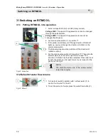
Page 18: ...o position 0 Select voltage converter 2 230V 400V Set main reverse switch 1 to position 1 Press pushbutton Control voltage ON 15Connections RITMO XL 15 1Connections for water and air 4 3 2 1 Fig 13 Co...

Page 19: ...off via the pressure cutoff 16 2Pump motor selector switch Fig 16 Operating modes of pump motor The pump motor has three operating modes Selector switch position 0 The machine is switched off Selector...

Page 20: ...o 20 11 84 00 Remixer for better inclusion and mixing of the material Direct drive through the pin of the rotor Content approx 4 2 l Uniform consistency Removable mixing wing Remixer can be opened for...

Page 21: ...t initial after pressure 1 bar Maximum media and ambient temperature 75 C Installation position unimportant preferably horizontal 18 2 Purpose of solenoid valve Application range Solenoid valves for l...

Page 22: ...Intended use of air compressor 19 1 Purpose of air compressor The equipment has been designed and constructed only for the intended use described below Caution The air compressor is only intended for...

Page 23: ...r corresponds to the national and international safety regulations and can therefore also be used in damp rooms or in the open air Areas with as clean and dry air as possible should be preferred Make...

Page 24: ...omatically ensured from a water tank by the PFT pressure booster pump for the constant water supply to the PFT machine engineering The flow pressure of min 2 5 bar when the machine is running is ensur...

Page 25: ...ssible 22Initial operation filling the pump Fig 27 Filling the pump Before putting the PFT High Pressure Pump into operation for the first time fill the pump with water so that the air in the pump hou...

Page 26: ...here is still air in the pump and this has to be completely vented again The suction line is not air tight and the pump is drawing in air The suction side screen is clogged The suction hose is kinked...

Page 27: ...ump shafts PFT mortar hoses are to be used These are made for each other and form a constructive unit with the machine Non observation will not only make the warranty null and void the user must also...

Page 28: ...d swiveling components pose danger to life Never stand under unstable loads Observe the specifications of the provided tying points Do not lift loads at projecting machine components or components att...

Page 29: ...mplaint periods 27 3Transport in single parts 1 Fig 31 Open rotation lock Fig 32 Mixing pump unit 1 For easier transportation dismantle the machine into its individual parts 2 Detach the units mixing...

Page 30: ...tion Observe the following conditions Crane and lifting devices must be designed to support the weight of the packages The operator must be authorized to operate the crane Remove all loose parts 1 in...

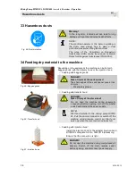
Page 31: ...ccordance with the expected transport conditions Environment friendly materials were used for packaging The packaging should protect the individual components from transport damages corrosion and othe...

Page 32: ...operating instructions document Ensure before starting work that all the covers and safety devices are installed and functioning properly Never disable safety devices during operation Pay attention t...

Page 33: ...y NOTE The machine can although it is connected to a 400V 3 phase AC power supply switched to 230V 1 phase and operated See page 15 Fig 14 Advantage The motor speed can be regulated through the potent...

Page 34: ...in 3 x 2 5mm must be used PFT power cable 3x2 5mm Article No 20423400 30 2 Check the individual connectors 1 2 Fig 38 Power connections Connection delivery hood 1 Check connection of air compressor 2...

Page 35: ...ent the water hose of the water supply line 7 Connect water hose and water inlet 3 8 Remove water hose 4 from mixing tube NOTE Use clean water free of solids only The minimum pressure when the machine...

Page 36: ...ne must change the direction of rotation in the main reverse switch 4 The following steps must be performed if the direction of rotation is wrong 5 Set the main reverse switch 2 to position 0 Then sli...

Page 37: ...l the consistency of the material is restored 31 3 Watering the mixing zone 3 2 1 Fig 46 Watering the mixing zone NOTE The pump must generally be flushed with water Flushing with water makes it easier...

Page 38: ...ng with bagged goods DANGER Risk of injury at the sack opener The sharp edges of the sack opener pose a risk of injury Wear safety gloves Fig 50 Transfer hood Feeding with transfer hood DANGER Risk of...

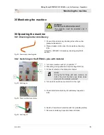
Page 39: ...nsistency checking tube 25M section 36 2 Switching on the RITMO L plus with material Fig 53 Switching on 1 Turn main reverse switch 1 to position I 2 Press the green pushbutton Control voltage ON 2 3...

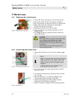
Page 40: ...and lead to serious injuries especially eye injuries Hoses that tear off can lash wildly and injure those standing nearby 37 2 Connecting the mortar hose Fig 57 Connecting the mortar hose 1 Connect t...

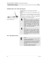
Page 41: ...hose couplings while the compressed air hose is pressurised 38 2 Connecting the spray gun 2 3 1 4 Fig 60 Spray gun 1 Connect compressed air hose 1 to the spray gun 2 2 Make sure that the air valve 3 o...

Page 42: ...ered we recommend applying mortar on the wall surface from top to bottom Uniform mixing and spreading is not ensured if the water quantity is inadequate the hose can get blocked which causes a high de...

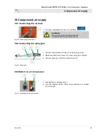
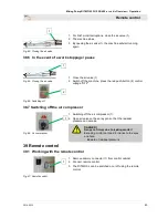
Page 43: ...f the machine press the red push button 2 control voltage OFF 38 7 Switching off the air compressor Fig 66 Air compressor 1 Switching off the air compressor 1 2 Open air valve on the spray gun so that...

Page 44: ...one and carry out first aid measures 6 Ensure emergency vehicles have unobstructed access 7 If the seriousness of the emergency warrants this inform the responsible authorities 8 Assign specialist per...

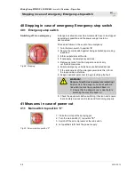
Page 45: ...a with foil 1 Open air tap on the spray gun 2 Check the mortar pressure gauge 1 to see if the pressure has fallen to 0 bar If necessary discharge any mortar pressure by unscrewing the nuts 2 slightly...

Page 46: ...OTE A table below lists particular malfunctions and who is authorised to handle them 42 2Fault displays Fig 72 Fault displays The following device indicates fault Item Luminous signal Description 1 Ye...

Page 47: ...w control lamp direction of rotation fault lights up On the main reverse switch push the metal clamp in the reverse direction Operator Motor circuit breaker tripped In the control cabinet turn the mot...

Page 48: ...long or suction pressure is too weak If possible prefix additional pressure boosting pump Service mechanic Machine does not switch off Air pressure safety switch is not in correct position or is defe...

Page 49: ...e flange Replace pressure flange Service mechanic Not original PFT spare parts Use original PFT spare parts Service mechanic Water ascends in mixing tube during operation Backlog pressure in mortar ho...

Page 50: ...Clogging of pressure flange Marked tapering at couplings Kink in mortar hose Difficult to pump and not properly mixed materials 43 3Pre existing damage in mortar hose NOTE During a machine fault if th...

Page 51: ...er and injure the operator Only open the mortar hoses if the mortar pressure gauge 1 indicates the pressure has fallen to 0 bar DANGER Danger of injury due to leaking mortar Escaping mortar can lead t...

Page 52: ...against restarting DANGER Danger of death due to unauthorised restarting When working on the machine there is a danger of unauthorised switching on of the electrical supply This puts those in the dan...

Page 53: ...nnect the cleaner coupling 1 to the water outlet valve 2 2 Press the water soaked sponge ball 3 into the mortar hose 4 3 Connect mortar hose 4 with the sponge ball to the cleaner coupling 1 7 6 5 Fig...

Page 54: ...release fastener 2 on the motor tilt flange and tilt the motor NOTE While performing cleaning jobs and during motor transport the housing with the safety cover 3 must be closed protection against humi...

Page 55: ...NGER Danger of getting crushed at the motor tilt flange While closing the motor tilt flange there is danger of getting crushed Do not reach into the closing area of the motor tilt flange 5 Fig 87 Clea...

Page 56: ...ing zone out of the material hopper and clean 2 Reinsert or mount rubber mixing zone and pump unit after cleaning 3 Ensure that the parts fit correctly 46 8 Inserting the mixing shaft Fig 90 Rotor sea...

Page 57: ...Removing the mixing shaft 3 Take mixing shaft 3 out of the mixing zone 4 Fig 94 Opening the outlet tap 4 Open outlet taps 4 on the fitting block 5 Allow water to drain off and close outlet taps again...

Page 58: ...he maintenance works described here can be carried out by the operator unless marked otherwise Some maintenance work must only be carried out by specially trained technical personnel or exclusively by...

Page 59: ...re Before starting work switch off all electrical power supplies and secure them against being switched back on again 48 3 Environmental protection Observe the following environmental protection guide...

Page 60: ...ng sieve Fig 99 Dirt trapping sieve in the water inlet Check dirt trapping sieve in the water inlet daily 1 Take out dirt trapping sieve from the Geka coupling 2 Clean dirt trapping sieve 3 Replace si...

Page 61: ...3 2 bar See PFT air compressor DELTA 2 230V with pressure switch off Article number of operating instructions 00 19 96 67 49 6Measures after maintenance After completion of maintenance jobs perform t...

Page 62: ...ficient free space before starting work Handle open sharp edged components carefully Pay attention to cleanliness and order at the workplace Components and tools lying loosely on each other or lying s...

Page 63: ...as remaining processing materials and dispose of them in an environment friendly manner 50 3Disposal Recycle the dismantled components If no return or disposal agreement was signed Scrap metals Recycl...

Page 64: ...54 Dealing with malfunctions 46 Decouple mortar hose 53 Default of water flow volume 36 Description of assemblies 17 Description of the PFT pressure booster pump accessories 24 Description RITMO XL 23...

Page 65: ...er 21 Purpose of solenoid valve 21 Putting RITMO XL into operation 36 Putting the pressure booster pump into operation 25 Relieve mortar pressure 45 Remedying hose blockages Signs of blockages 50 Remo...

Page 66: ...ump RITMO XL FU 230 400 reversible Overview Operation 66 2019 05 13 Water from water barrel 35 Water pressure switch 61 Water selector switch 19 Watering the mixing zone 37 Working with the remote con...

Page 67: ...Mixing Pump RITMO XL FU 230 400 reversible Overview Operation 2019 05 13 67...

Page 68: ...Operation 68 2019 05 13 PFT THE FLOW OF PRODUCTIVITY Knauf PFT GmbH Co KG Postfach 60 97343 Iphofen Einersheimer Stra e 53 97346 Iphofen Germany Telephone 49 9323 31 760 Telefax 49 9323 31 770 Technic...

Reviews: