background image


3)76:,1*

*%

0RUWDU3XPS

9HUVLRQ

BBBBBBBBBBBBBBBBBBBBBBBBBBBBBBBBBBBBBBBBBBBBBBBBBBBBBBBBBBBBBBBBBBBBBBBBBBBBBBBBBBBBBBBB


________________________________________________________________________________________ 


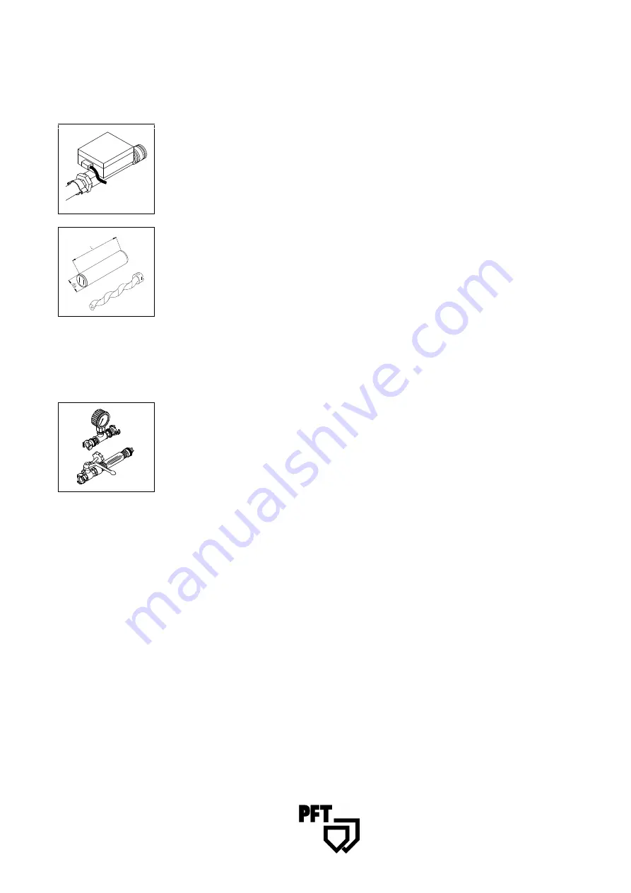
)ORZ'HWHFWRU

Monitors the air flow from the compressor to the spray gun / paint gun and switches 

the pump on as soon as air flows through the line. 

 
The dummy plug of the remote control has to be disconnected


3)76:,1*,,38036<67(0

The standard equipment of the PFT SWING II includes a maintenance-free pump 

system. 

127(

Rotor and stator are wearing parts, which have to be regularly inspected and replaced 

if necessary. 

3UHVVXUH


The pump unit 

3)76:,1*,,

 should provide a pressure of at least 15-20 bar. When 

the machine is switched off, the back pressure should be approx. 6-8 bar. 


0RQLWRULQJWKHFRQYH\LQJSUHVVXUHDQGEDFNSUHVVXUH


  Fill the material container of the pump with water 

  Connect a 10 m conveying hose 

  Connect a mortar pressure gauge 

  Attach a spray gun with a ball tap to the end of the hose 

  Open the ball tap 

  Switch the machine on and wait until water flows out of the spray gun (deaerate 

the hose) 

  Close the ball tap 

  Let the pump run against pressure until the pressure does not rise any more 

  If the necessary pressure of 15-20 bar is not reached, the pump has to be 

replaced 

  Check the back pressure 


:KHQLQVWDOOLQJUHPRYLQJWKHSXPSXQLWNHHSLQPLQGWKDW


  The machine must be disconnected from the power supply during (dis-)assembly. 

  A new stator and a new rotor require a running-in period, and reliable pressure 

values can only be determined after one spraying operation. 

  Pump components that neither provide the necessary conveying pressure nor 

maintain the required back pressure are worn out and have to be replaced. 


Summary of Contents for SWING II

Page 1: ...23 5 7 1 0 18 219 1 3803 3 7 6 1 WE KEEP THINGS MOVING...

Page 2: ......

Page 3: ...will be a reliable helper under the tough conditions of construction sites This operating manual should always be at hand in the place of use of the machine It informs you about the various functions...

Page 4: ...of the first spraying operation Factory settings may change during the initial operation If these changes are not corrected in time i e right after the running in period malfunctions are likely to occ...

Page 5: ...8 00 301 Overview Control Box 5 08 00 302 Functional Description 5 08 00 303 Basic Safety Instructions 5 08 00 401 Mortar Pump 5 08 00 403 Initial Operation 5 08 00 405 Intermission 5 08 00 408 Measur...

Page 6: ...BBBBBBBBBBBBBBBBBBBBBBBBB ________________________________________________________________________________________ 1 Material container 7 Pump shaft 2 Protective grating 8 Rotor 3 Holder for control b...

Page 7: ..._______________________________________________________________ 1 ON OFF Switch 7 Socket for pump Motor 2 Control light green operation ON 8 Air connection for compressor 3 Selector switch for directi...

Page 8: ...SOLFDWLRQ JXLGHOLQHV RI WKH PDWHULDO PDQXIDFWXUHUV The machine consists of portable components permitting quick and easy transport thanks to their small handy dimensions and low weights Observe the fo...

Page 9: ...age 51 1 The machine should only be used in a technically faultless state for the specified purposes in the awareness of the safety guidelines and potential dangers and in accordance with the operatin...

Page 10: ...reading indicator signals 9 When the machine is completely switched off for maintenance and repair work it has to be secured against unexpected restarting e g by locking the main switch and removing t...

Page 11: ...prox 6 8 bar 0RQLWRULQJ WKH FRQYH LQJ SUHVVXUH DQG EDFN SUHVVXUH Fill the material container of the pump with water Connect a 10 m conveying hose Connect a mortar pressure gauge Attach a spray gun wit...

Page 12: ...h degree of operator safety Longevity of the PFT pump components 127 1 Stator SWING II can be used at operating pressures of up to 20 bar 2 The possible conveying distance largely depends on the flowa...

Page 13: ...QW FLUFXLW EUHDNHU P RUNLQJ ZLWK 3DLQW 5ROO 6HW IRU 6 1 Disconnect dummy plug from control box Connect remote control cable switch OFF Connect mortar pressure gauge Screw the paint roller on the teles...

Page 14: ...t gun Connect compressor with air pipe to control box Separately connect compressor to power supply and switch it on wait until pressure has built up in the air hose Fill hopper with paint or similar...

Page 15: ...or similar materials Push green ON button Control lights is on Select medium speed scale value 3 Turn selector switch to forward position Open material tap and then air tap on spray gun This air flow...

Page 16: ...the hoses with lime milk depending on the guidelines of the material producer The conveying pump 3 7 6 1 can be filled with the aid of a continuous mixer e g HM 2002 HM 22 24 HM 200 HM 5 or the like o...

Page 17: ...stic sheet or similar material Slightly loosen the tie rods of the pressure flange so that any residual pressure can be completely eliminated Unscrew the hose coupling Clean the hose To remove residua...

Page 18: ...se water may penetrate the bearings switches sockets plugs etc and cause damage Clean the material container Discharge dirty water through the cleaning opening Flush the pump with clean water Rinse th...

Page 19: ...ting ON contact element faulty Fault lamp lights up Fine fuse faulty Pump stuck Release pump by running it in reverse Operation with Compressor Air flow detector misadjusted Air regulation valve on sp...

Page 20: ...______________________________________ 3 7 RQWDFW 0DNLQJ 3UHVVXUH DXJH 6 1 IRU 3DLQW RPSOHWH UW QR Machine is automatically switched off when the selected mortar pressure is exceeded Range of control...

Page 21: ...QR consisting of 00 00 84 78 Material Pressure Hose 12 5 mm 15m 00 00 85 21 PVC Hose 15m 00 00 85 88 Paint Gun SWING 00 01 04 11 Sponge ball diameter 17mm 3 7 6SUD LQJ TXLSPHQW 6 1 LQ DVH UW QR consi...

Page 22: ..._________________________ 0 1 2 3 4 5 6 7 8 9 A BC D DE F G H DE F I I 6 J 3 4 5 7 8 9 K L M N O P L Q K RS TU V W WW X YZ I 2 Y _ a b c dfe g h h i adj h k h lm i n n k h l g b h n n d e oj m ij ph q...

Page 23: ...______________________________________________________________________________ Spare Part List Drive Assembly 3 01 00 702 Spare Part List Material Container Assembly 3 01 00 704 Spare Part List Pump a...

Page 24: ...SDUH 3DUW LVW ULYH 8QLW 9HUVLRQ BBBBBBBBBBBBBBBBBBBBBBBBBBBBBBBBBBBBBBBBBBBBBBBBBBBBBBBBBBBBBBBBBBBBBBBBBBBBBBBBBBBBBBBB _______________________________________________________________________________...

Page 25: ...2 00 04 42 22 Sealing washer USIT 8 7 x 13 x 1 NBR V2A 7 2 20 20 93 13 Plain washer B 8 4 DIN 125 galv 8 1 20 14 40 32 Oil level glass R1 2 with seal 9 1 00 00 84 71 Sealing housing SWING 10 2 00 00...

Page 26: ...UW LVW 0DWHULDO RQWDLQHU VVHPEO 9HUVLRQ BBBBBBBBBBBBBBBBBBBBBBBBBBBBBBBBBBBBBBBBBBBBBBBBBBBBBBBBBBBBBBBBBBBBBBBBBBBBBBBBBBBBBBBB _______________________________________________________________________...

Page 27: ...xagon head screw M 8 x 20 DIN 933 galv 9 1 00 02 33 42 Hexagon head nut M 16 x 1 5 DIN 439 bare 10 1 00 01 07 92 Stop bolt M 16 x 1 5 11 1 00 03 71 91 Material container SWING II 12 2 20 20 93 15 Plai...

Page 28: ...LVW 3XPS O PLQ DQG 6KDIW VVHPEO 9HUVLRQ BBBBBBBBBBBBBBBBBBBBBBBBBBBBBBBBBBBBBBBBBBBBBBBBBBBBBBBBBBBBBBBBBBBBBBBBBBBBBBBBBBBBBBBB ______________________________________________________________________...

Page 29: ...0 01 08 87 Serrated lock washer A 8 4 DIN 6798 A2 17 1 00 02 32 18 Hexagon head bolt M 10 x 80 DIN 931 galv 18 1 20 20 72 10 Lock nut M 10 DIN 985 galv 19 1 00 00 84 63 Rotor B 4 2 SWING I 4 litres 20...

Page 30: ...LVW 3XPS O PLQ DQG 6KDIW VVHPEO 9HUVLRQ BBBBBBBBBBBBBBBBBBBBBBBBBBBBBBBBBBBBBBBBBBBBBBBBBBBBBBBBBBBBBBBBBBBBBBBBBBBBBBBBBBBBBBBB ______________________________________________________________________...

Page 31: ...00 01 08 87 Serrated lock washer A 8 4 DIN 6798 A2 17 1 00 02 32 18 Hexagon head bolt M 10 x 80 DIN 931 galv 18 1 20 20 72 10 Lock nut M 10 DIN 985 galv 19 1 00 03 71 87 Rotor C 4 2 SWING II 8 litres...

Page 32: ...H 3DUW LVW RQWURO R VVHPEO 9HUVLRQ BBBBBBBBBBBBBBBBBBBBBBBBBBBBBBBBBBBBBBBBBBBBBBBBBBBBBBBBBBBBBBBBBBBBBBBBBBBBBBBBBBBBBBBB ____________________________________________________________________________...

Page 33: ...wo pin earthed plug rubber 16 1 00 03 63 44 Control transformer 230 V 42 V EV10 0 07 A 17 1 20 44 81 20 Coupling relay 42 V 2 change over contacts 18 1 20 45 59 04 Contact element EK10 1 make contact...

Page 34: ...nt Schuko plug earthing Fuse protection 1 phase 10 A slow Pumping capacity Pump type SWING 4 l min 0 4 4 l min Pump type SWING II 8 l min 0 8 8 l min Conveying distance approx 15m Operating pressure m...

Page 35: ......

Page 36: ...32 59 PFT Systems Vertriebs GmbH Sucursal en Espa a Pgno Ind Ipertegui E 31 160 Orcoyen Navarra Tel fono 948 32 50 37 Telefax 948 32 50 33 PFT Systems Vertriebs GmbH A 8940 Wei enbach am Liezen Telef...

Reviews: