PFT Conveying Pump ZP 3 XL MIX Part 2 Overview – Operation - Spare Parts Lists
Putting the Drum Mixer into Operation
22
Fehler! Formatvorlage nicht definiert.
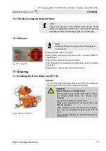
7.5 Material Hose Connection
Fig. 24: Material hose connection
Pour approx. two litres of lime slurry into the first material tube (1).
Connect all required material hoses together and moisten them
internally with the lime slurry.
Connect the material hose (1) to the pressure flange/mortar
pressure manometer (2).
HINT!
Pay attention to clean and correct connection of the
couplings!
Carefully fasten the riser pipes so that they do not
rupture under their own weight!
DANGER!
Ruptured hoses can strike around and injure the
bystanders!
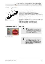
Fig. 25: Ready for operation
Turn the main reversing switch on "I".
Machine is operative.
8 Putting the Drum Mixer into Operation
8.1 Mixing Position for Drum Mixer
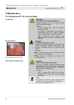
Fig.26: Locking disk
To mix mortar, the drum mixer must be in a certain mixing position
(inclination). The drum mixer is equipped with a locking disk with
slits. In the required mixing position, both noses must engage with
corresponding slits in the hand-wheel spokes (Fig. 26). The noses
are unlocked out of the slits and/or locked again into the slits,
which is done by tilting the hand wheel around its swivel axis.
HINT!
Do not place the drum mixer more steeply than
prescribed.
Only a correctly set up mixer and the correct mixing
positions ensure the best mixing results and
guarantee undisturbed workflow.
Filling and emptying may be undertaken only in a
running drum mixer.
2

