NewFEIMAS
Refer to Revision Record on page 2.
T.Anzai
Nov. 20, 2008
K.Okada
Rev
04
03
PAGE
73
/
138
PFU LIMITED
P1PA03334-B30X/6
Refer to Revision Record on page 2.
T.Anzai
July 7, 2008
K.Okada
Refer to Revision Record on page 2.
K.Okada
K.Okada
DESCRIPTION
CHECK
DATE
T.Anzai
APPR.
K.Okada
K.Okada
Aug.19, 2005
DESIG
N
DESIG
.
CUST.
I.Fujioka
I.Fujioka
T.Anzai
CHECK
fi-5530C/fi-5530C2
IMAGE SCANNER
MAINTENANCE MANUAL
APPR.
TITLE
DRAW.
No.
Feb.23, 2007
05
Section 4-9-1
4-9. Replacing the parts in the Upper Unit
4-9-1. Replacing the Panel PCA
Refer to
Section 6-22
for the part number of the replacement part.
<Removing>
(1)
Temporarily move the EEPROM data installed on the Panel PCA into the Control PCA (Refer to
Section 5-2
).
Note: EEPROM is installed on the Panel PCA instead of the Control PCA for this scanner to reduce the data saving
operations, since the Control PCA requires more frequent replacement than Panel PCA.
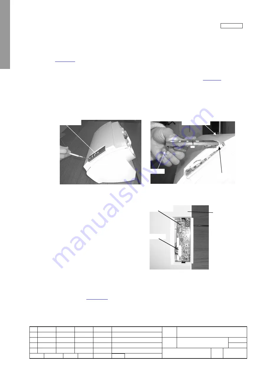
(2)
Insert a flat screwdriver into a gap of the Panel Cover and Upper Cover, and remove the Panel Cover by releasing a tab
from Upper cover as shown below.
(3)
Take out the Panel PCA and disconnect one connector from the Panel PCA.
<Mounting>
(1) Follow the removing procedure in reverse.
(2) After mounting a new Panel PCA, overwrite the EEPROM data that has been saved on the Control PCA into the new
Panel PCA. (Refer to
Section 5-1-8
.)
(3) Put the cables into the hole of Upper cover (see above photo). If the cables are accidentally placed between Panel PCA
and Upper cover, the Panel PCA is lifted causing power button to be turned ON.
Panel cover
Claw A
Tab
Upper cover
Connector
Panel PCA
Upper cover


