NewFEIMAS
Refer to Revision Record on page 2.
T.Anzai
Nov. 20, 2008
K.Okada
Rev
04
03
PAGE
74
/
138
PFU LIMITED
P1PA03334-B30X/6
Refer to Revision Record on page 2.
T.Anzai
July 7, 2008
K.Okada
Refer to Revision Record on page 2.
K.Okada
K.Okada
DESCRIPTION
CHECK
DATE
T.Anzai
APPR.
K.Okada
K.Okada
Aug.19, 2005
DESIG
N
DESIG
.
CUST.
I.Fujioka
I.Fujioka
T.Anzai
CHECK
fi-5530C/fi-5530C2
IMAGE SCANNER
MAINTENANCE MANUAL
APPR.
TITLE
DRAW.
No.
Feb.23, 2007
05
Section 4-9-2
4-9-2. Replacing the Inverter SR
P/N of replacement part is described in
Section 6-4
.
Conduct the procedure under dust-free environment.
<Removing>
(1) Remove Chute unit (ADF paper chute), Stacker unit, PCB unit and Upper cover by referring to
Sections 4-7-1
,
4-7-2
and
4-7-5
.
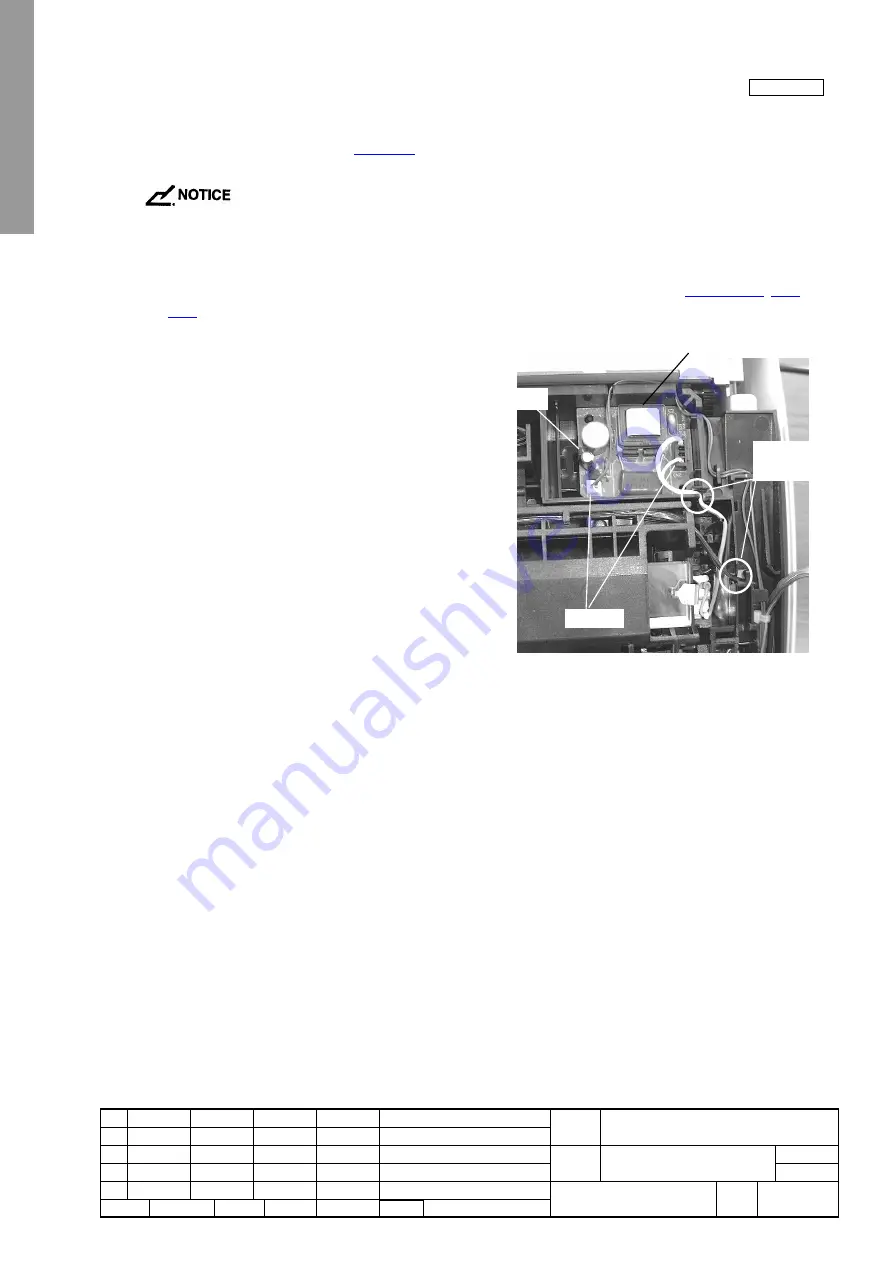
(2) Disconnect two connectors from Inverter SR, and detach
a craw to remove it.
<Mounting>
Follow the removing procedure in reverse. Makes sure the cables are placed through the slots in two locations as shown in the
figure above.
Claw
Inverter SR
Connector
Slots to route
the cable


