21
20
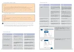
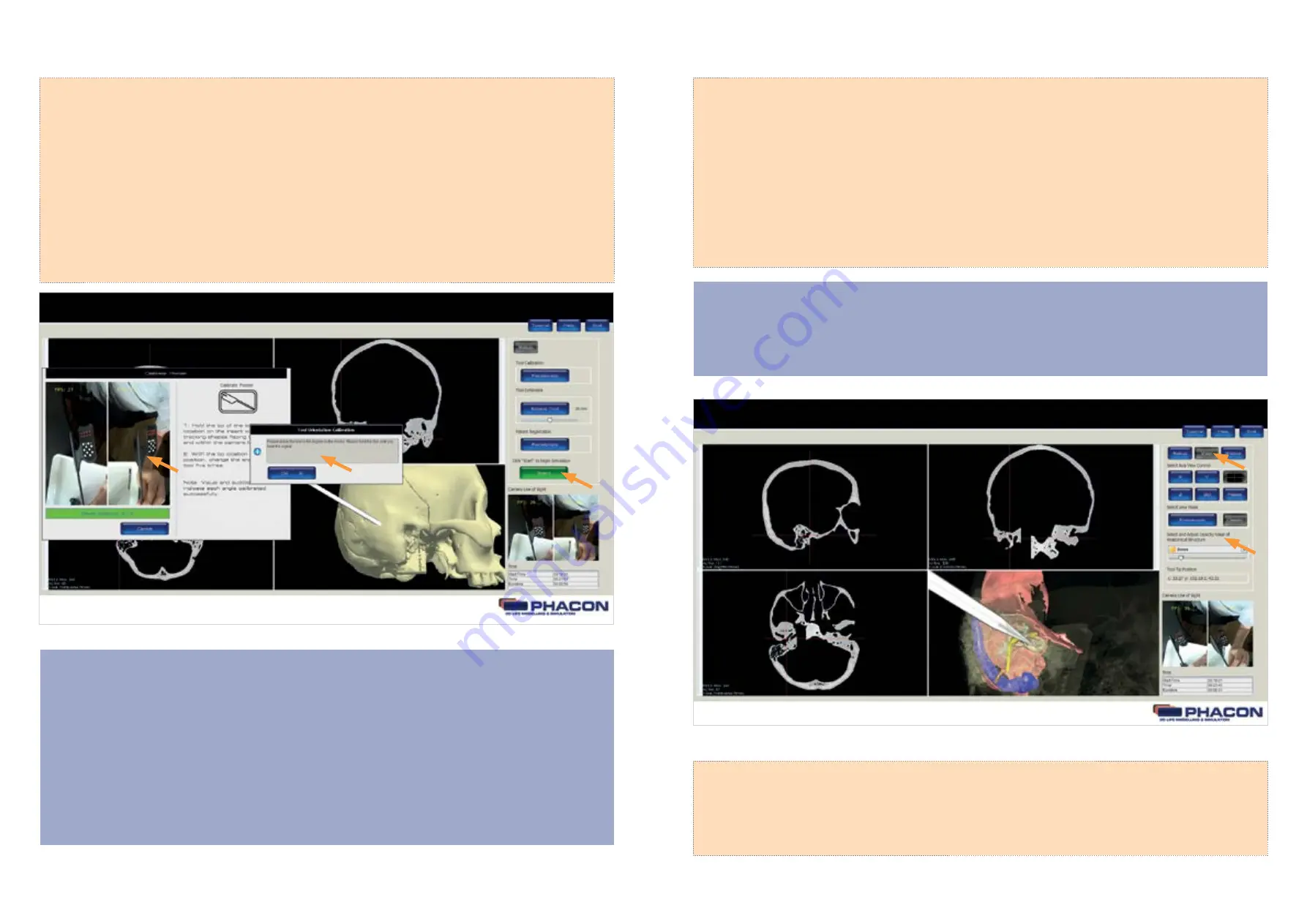
SELECT A VIEW DURING SIMULATION
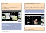
From the panel menu bar, click on the VIEW button to access the VIEW panel options including
AXIS VIEW CONTROL, VIEW MODE and the OPACITY VALUE of an ANATOMICAL STRUCTURE (Fig. 8).
NOTE
The cross hairs visible within each windowpane represent the location of the pointer, drill or
manual instrument tip when using navigation.
(Fig. 8)
PERFORM TOOL CALIBRATION
NOTE
• Tool Calibration* is performed to determine the axis length and tip location of the pointer, drill or
manual instrument.
• Orientation calibration is the last step of Tool Calibration. Orientation calibration is performed to
determine the orientation of the pointer, drill, or manual instrument within the 3-D space.
• ALWAYS keep the tip of the pointer, drill or manual instrument in the same user-defined location
during the entire calibration procedure.
• Sequence numbers and a progress bar are provided in the TOOL CALIBRATION dialog window as
visual feedback during the calibration procedure.
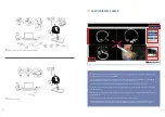
1. Click on the CALIBRATE or RECALIBRATE button to begin the calibration process. Make sure the desired
tool is selected for calibration.
2. Hold the tip of the tool in a fixed location on the Patient. Make sure the tracking shapes are facing the
camera and are within the camera line of sight.
3. After visual and audible feedback indicates successful data acq uisition, change the angle of the tool
while keeping the tip of the tool in a fixed location.
• Change the angle of the tool five times with the tip location in a fixed location.
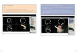
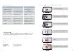
• Hold the tool perpendicular to the Patient to perform the direction calibration (Fig. 7 ). An INFORMA-
TION MESSAGE pop-up will appear to indicate the successful completion of the calibration
procedure.
• Perform the Patient CALIBRATION if necessary.
•
Click on the START or RESUME button to begin or continue the simulation, respectively, if desired.
Caution:
Please note during the tool calibration and in the further course no clothes with conspicuous pattern. Disturbing patterns on the clothing
can cause problems with the measurement and navigation.
(Fig. 7)
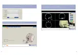
PERFORM PATIENT CALIBRATION (PHACON Temporal Bone Patient with skin)
NOTE
If you want to work with a PHACON Temporal Bone Patient with skin, you have to calibrate the
PHACON Temporal Bone Trainer bilateral with the provided calibration patient (PHACON Temporal
Bone Patient without skin) first. Therefore put the calibration patient into the head and follow the
instructions. After a successful calibration, exchange the calibration patient to the PHACON Temporal
Bone Patient with skin.


