background image

MAGNIUM

GEAR

03

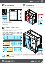
With all the panels removed, there is enough room to place all of 

your components. We’ll first start with the motherboard.

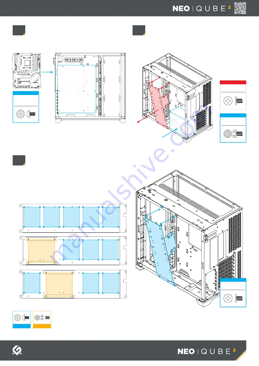
The HDD brackets can be positioned as shown in option 

B

 and 

C


or removed to allow for 5x 2.5” SSDs as option 

A

.

There are different configurations possible with the storage 

bracket. Below you see the configuarations as, 

A

B

 or 

C

. Use the 

provided SSD and/or HDD screws.

After the drives have been installed, place back the storage 

bracket onto the chassis and secure with 2x case screws.

Use the SSD screws to install the 2.5” 

SSD’s. The 3.5” HDD can be installed with 

the HDD screws.

Remove the storage bracket before installing the power supply. 

The power supply is then secured with 4x PSU screws.

03

05

04

Supported Motherboad form-factors are:

Mini-ITX | Micro-ATX* | ATX | E-ATX (up to 280mm wide)

*For Micro-ATX Motherboards, please re-position the stand-offs according to the 
motherboards’ manual.

PSU

2.5”

3.5”

3.5”

B

A

C

2.5”

2.5”

2.5”

2.5”

2.5”

2.5”

2.5”

2.5”

2.5”

2.5”

SSD Screw

HDD Screw

Case Screw

2x

REMOVE

PSU Screw

4x

INSTALL

Motherboard 
Screw

9x

INSTALL

Case Screw

2x

INSTALL

MOTHERBOARD

STORAGE INSTALLATION

POWER SUPPLY

Summary of Contents for Magnium Gear NEO Qube 2

Page 1: ... www magnium gear com or contact us through support magnium gear com Power Reset Becomes power button for dual system see DUAL SYSTEM section for more information D RGB color D RGB mode Headphones Mic USB C USB 3 0 USER MANUAL MODES Press and hold the MODE button for two seconds to turn off LEDs press again to turn it ON COLORS SOLID BREATHING SPARKLE MUTLI COLOR TURN OFF LEDs INCLUDED ACCESSORIES...

Page 2: ...his for both top panels Lift the side front panel upwards 4 before pulling it away from the chassis Both side and front panels are removed in the same way 01 02 2 1 3 4 REMOVING CHASSIS PANELS REMOVING SIDE FRONT PANELS WARNING FOR NEO QUBE 2 IM Please be careful when removing the front panel the infinity mirror coating is sensitive to fingerprints and not easy to clean ...

Page 3: ... onto the chassis and secure with 2x case screws Use the SSD screws to install the 2 5 SSD s The 3 5 HDD can be installed with the HDD screws Remove the storage bracket before installing the power supply The power supply is then secured with 4x PSU screws 03 05 04 Supported Motherboad form factors are Mini ITX Micro ATX ATX E ATX up to 280mm wide For Micro ATX Motherboards please re position the s...

Page 4: ...ng can be expanded with more lighting products using the two available connectors Additionally the lighting can be controlled from a compatible motherboard D RGB CABLES EXPAND WITH MORE D RGB PRODUCTS CONTROL LIGHTING FROM THE MOTHERBOARD MOTHERBOARD FRONT I O HEADER DIAGRAM 06 I O CABLES The PHANTEKS REVOLT X PSU is required for a Dual System Install 4x Motherboard Stand offs Secure the Mini ITX ...

Reviews: