13
12
Phantom Flex Manual
Phantom Flex Manual
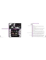
Viewfinder
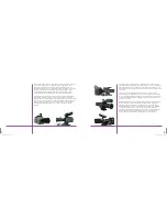
Mount the viewfinder on the bracket at the front of the camera’s handle.
Connnect the viewfinder cable to the viewfinder socket on the right side
of the camera.
Powering the Camera
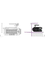
Connect a 24v power source the either of the inputs on the back of the camera.
There is no power switch the camera will turn on when power is connected.
Powering 12v accessories
–Two 12v accessory outputs are provided
on the side of the camera. Each provides up to 1.5A (approx 18 watts).
Remote trigger
Any closed contact switch can be used as a trigger thru this BNC connector.
Momentary closed contact switch can be used for trigger in loop mode;
a continuous closed contact switch is required for recording in run/stop mode.
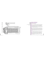
To be controlled by a computer, the Phantom Flex needs to be on the same
Ethernet network as the computer. All Phantoms are preset with permanent
IP addresses on the same subnet. A computer needs to be on the same
subnet to communicate with the camera.To ensure this, set the computer’s
address to 100.100.100.1 with a subnet mask of 255.255.0.0.
There are 2 HDSDI outputs on the rear of the camera. In 4:2:2 mode, output 1
is always a clean feed, with no characters.The characters can be enabled
or disabled on output 2 by enabling the SDI OSD (On Screen Display) in the
PVP software. (See chapter 6). When the camera is set to output 4:4:4,
outputs 1 and 2 become the A and B links of a single dual-link output.
Building the Camera
Connecting a Computer
Monitoring
Camera Set Up
4
A
B
C
D
E
F
A
B
C
D
F
G
H
Summary of Contents for Flex
Page 1: ...MANUAL ...
Page 2: ...MANUAL New York Chicago Los Angeles First Edition 09 20 10 www abelcine com ...
Page 52: ...94 Phantom Flex Manual ...
Page 53: ......


