background image

Installing the 

Top Rail 

and 

Catch Frame


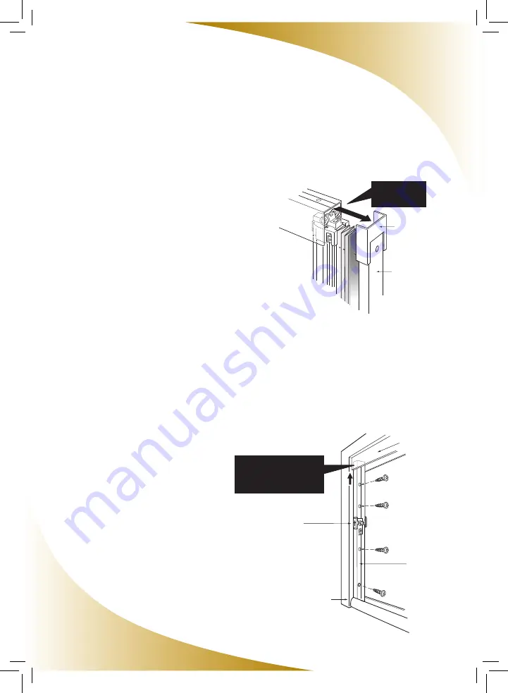
Installing the Top Rail

1.   Remove the backing of the adhesive tape on the  
 

top of the Top Rail.

2.   Insert the Rollers at the top of the Sliding Bar  
 

into the Top Rail, then push the Top Rail into the  


Corner Cover on the top of the   


Mounting Bracket.

3.   Position the Top Rail along the top of the door  
 

frame at a 90º angle to the side   


mounting surfaces.

4.   Making sure that the Top Rail is tight against the  
 

side of the door frame opposite the  


Mounting Bracket, press firmly in place,  


allowing the adhesive tape to temporarily hold  


it in place.

5.   Using the 5/8” (16mm) screws provided, secure  
 

the Top Rail to the door frame.

Installing the Catch Frame

1.   Insert the bottom of the Catch Frame inside the    
 

Bottom Rail and the top of the Catch frame into the  


Top Rail.  Position it against the door frame on    


the opposite side of the Screen Housing Assembly.

2.   Lift the Catch Frame upward into the Top Rail    
 

as far as it will go, and secure to the door frame    


using the provided wood screws.

Top Rail

Catch Frame

Latch

Door Frame

Push up the top of the

Catch Frame all the way

into the Top Rail

10

Push in

to the

Corner C

over

Corner Cover

Mounting Bracket

Insert Rollers

as shown

Summary of Contents for Viewpoint VI0508

Page 1: ...Installation Manual for For Right and Left Hinged Doors Durable Reliable Attractive For door openings up to 36 914 mm wide and 80 9 16 2 047 mm high Quick and Easy to Size and Install ...

Page 2: ...oud to bring you these innovative products Thanks to rigorous design and product testing the Viewpoint Screen will provide years of dependable operation Plus it comes with a factory supplied limited lifetime warranty on all parts against manufacturer s defects Viewpoint was designed for easy sizing and installation This Installation Manual provides a step by step guide through the entire process A...

Page 3: ...il and Catch Frame Adjusting the Latch and Tension Wires Attaching the Fixing Strip and Installing the Clips Service and Maintenance Hints Index For installation on a double hinged door French Doors you will need two Viewpoint Screens and one Double Door Kit Please refer to the Installation Manual within the Double Door Kit prior to starting The Viewpoint Screen is not intended for installation on...

Page 4: ...rame to reduce the height of the door opening Refer to page 6 for details NOTE The Viewpoint Screen can only be shortened by 4 100 mm to a minimum height of 76 9 16 1 947 mm If the door opening is smaller than this the Viewpoint Screen will not accomodate the door 4 Is the Door Opening Square For the Viewpoint Screen to operate effectively the door opening must be perfectly square Using a Carpente...

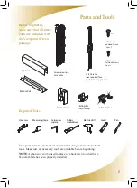
Page 5: ... beginning NOTE A chop saw can be used in place of a hacksaw provided that a bi metal blade has been properly installed 5 Top Rail Bottom Rail Screen Housing Assembly Catch Frame not required for a double door application 5 8 16 mm Pan Head Screws 12 pcs 1 2 12 mm Flat Head Screws 2 pcs me over g Bracket ip Wire Rail Hack saw Philips screwdriver Electric drill Measuring tape Level Carpenter square...

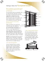
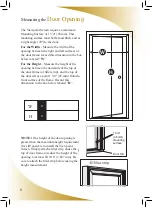
Page 6: ... between the underside of the top of the door frame or filler strip and the top of the door sill at a point 1 3 4 45 mm from the front surface of the frame Record this dimension in the box below labeled H NOTE If the height of the door opening is greater than the maximum height requirement it is still possible to install the Viewpoint Screen Simply attach a filler strip under the top of door frame...

Page 7: ...om the bottom of the unit note the Cut No Cut labels No more than 4 100 mm can be cut from the Screen Housing Assembly Maximum Opening Height Subtract inside door frame height H Enter Cut off Length Below 80 9 16 2 047 mm Cut from each part the cut off length provided by the calculation performed above Do NOT remove the tape that keeps the components of the Screen Housing Assembly secure until all...

Page 8: ...e Screen Housing Assembly 1 Before installing the Screen Housing Assembly rotate the Mounting Bracket so that the Tension Wires are no longer wound around it Failing to do so prior to installing the Mounting Bracket will restrict the motion of the Tension Wires and prevent the screen from operating 2 Attach the Sliding Bar Bottom Cap to the bottom of the Sliding Bar using the two screws provided 3...

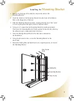
Page 9: ... portion of the door frame 4 Using a level ensure that the Mounting Bracket is positioned plumb Then press the Mounting Bracket firmly against the door frame allowing the adhesive tape to temporarily hold it in place 5 Move the Sliding Bar and Mesh off to the side as indicated in the illustration 6 Using the provided screws secure the Mounting Bracket to the door frame 7 Return the Sliding Bar and...

Page 10: ...ss firmly in place allowing the adhesive tape to temporarily hold it in place 5 Using the 5 8 16mm screws provided secure the Top Rail to the door frame Installing the Catch Frame 1 Insert the bottom of the Catch Frame inside the Bottom Rail and the top of the Catch frame into the Top Rail Position it against the door frame on the opposite side of the Screen Housing Assembly 2 Lift the Catch Frame...

Page 11: ...e it NOTE do not over tighten the tension on the Tension Wire 2 If any of the other Tension Wires are sagging perform the same procedure with each adjuster If any of the situations below occur follow the appropriate procedure to correct the situation After adjusting the tension move the Sliding Bar two or three times to check the operation of the Viewpoint Screen Loosen the screw to move up and do...

Page 12: ...e of the Fixing Strip into the Mounting Bracket working it into position all the way to the bottom so that it is now fully inserted into the Mounting Bracket Installing the Clips Install the Clips into the Mounting Bracket evenly between the Tension Wires keeping the ribbed face of the Clip facing outward Refer to the diagram The Viewpoint Screen Installation is Now Complete Mounting Bracket Fixin...

Page 13: ...oducts attract dirt and debris and may cause the Viewpoint Screen to react abnormally However the periodic application of a dry silicon lubricant to the moving parts is permissible We recommend that while not in use the Viewpoint Screen be kept in the retracted position This will help extend the life of the screen mesh In the retracted position the mesh is protected and kept clean The Screen Mesh ...

Page 14: ... designed for easy sizing and installation This Installation Manual provides a step by step guide through the entire process If there are any questions during the installation of the Viewpoint Screen please call toll free 1 877 446 7180 14 ...

Page 15: ...balance of the original warranty period Seiki Screen Systems liability under this limited warranty is restricted to the corrective actions as set forth herein and contrarily repudiates all incidental and consequential damage It is the responsibility of the consumer to notify Seiki Screen Systems of missing components within 30 days of the purchase of the Viewpoint Screen The Viewpoint Screen is de...

Page 16: ...Phantom Screens Seiki Screen Systems Call 1 877 446 7180 Or email info seikiscreensystems com www seikiscreensystems com Phantom Mfg Int l Ltd Call 1 888 PHANTOM Or email phantom phantomscreens com www phantomscreens com 2008 Phantom Mfg Int l Ltd Seiki Screen Systems VI0508 ...

Reviews: