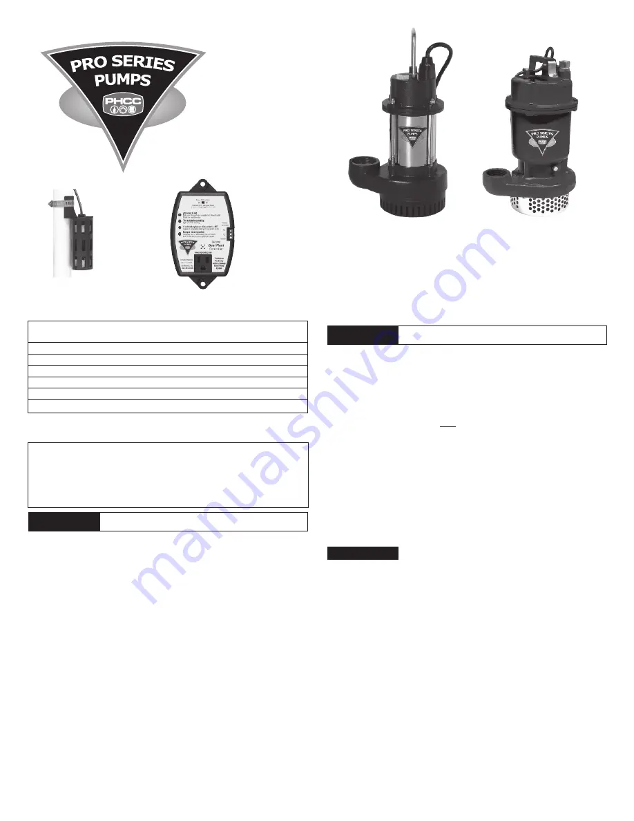
S5 Series
Dewatering Sump Pumps
5 Year Warranty
PHCC Pro Series
Sump Pumps
Instruction Manual
& Safety Warnings
Important Safety Instructions and Warnings
SAVE THESE INSTRUCTIONS.
This manual contains important SAFETY WARNINGS and
OPERATING INSTRUCTIONS for the PHCC Pro Series pumps. You will need to refer to it
before attempting any installation or maintenance.
ALWAYS
keep these instructions with the unit so that they will be easily accessible.
Failure to read and follow these warnings and instructions could result in property
damage, serious injury, or death.
•
ALWAYS
disconnect the pump from the power source before servicing or making
adjustments.
•
NEVER
handle the pump or motor with wet hands or when standing on a wet or damp
surface while the pump is plugged into the power source.
•
MAKE SURE THERE IS A PROPERLY GROUNDED RECEPTACLE AVAILABLE.
This pump is
wired with a 3-prong grounded plug. To reduce the risk of electric shock, be certain
that it is only connected to a properly grounded, 3-prong receptacle. If you have a
2-prong receptacle, have a licensed electrician replace it with a 3-prong receptacle
according to local codes and ordinances.
•
NEVER
bypass grounding wires or remove the ground prong from the plug.
•
DO NOT
use an extension cord. The electrical outlet should be within the length of the
pump’s power cord, and at least 4 feet above the floor level to minimize potential
hazards from flood conditions.
•
DO
protect the electrical cord from sharp objects, hot surfaces, oil, and chemicals.
Avoid kinking the cord.
•
MAKE SURE
the supply circuit has a fuse or circuit breaker rated to handle the power
requirements noted on the nameplate of the pump.
•
DO NOT
remove the power supply cord and strain relief or connect the pump directly to
the conduit.
•
NEVER
install the pump in locations classified as hazardous in accordance with the
National Electrical Code, ANSI/NFPA 70.
•
ALWAYS
install the pump in accordance with the National Electric Code and all
applicable local codes and ordinances. All wiring should be performed by a licensed
electrician.
•
DO NOT
use the power cord or strain relief to carry the pump. Use the pump handle.
•
DO NOT
expose the control unit to any type of moisture, water, rain or snow.
•
DO NOT
operate the pump or control unit if it has been damaged in any way.
•
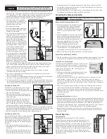
DO drill an air bleed hole in the discharge pipe when a check valve is used. Drill
the hole angled toward the bottom of the sump to avoid splashing water outside
the sump pit. If a hole is not drilled above the pump, an air lock may prevent the
pump from operating. The hole must be drilled above the water line but below the
check valve. The optimum size of the hole is different for different pumps. Drill a
1/8” (3.2mm) hole in the discharge pipe for the S3 Series and S5 Series pumps.
•
DO NOT
use sump pumps in pits handling raw sewage, salt water, or hazardous liquids.
S3 & S5 Series pumps are not designed for this purpose. The S3 and S5 Series sump
pumps are designed for ground water use only.
•
DO NOT
disassemble the pump or control unit. When service is required, contact
Glentronics technical support at 800-991-0466, option 3. Return the product to the
manufacturer for any repairs at the following address:
Glentronics, Inc.
645 Heathrow Drive, Lincolnshire, IL 60069
• The control unit must receive 115V AC +/- 5% and 60 Hz from the AC outlet. Lower
voltage may cause the power failure alarm to activate.
• These primary pumps will not provide protection during a power outage. With the risk of
property damage from high water levels, the addition of a PHCC Pro Series battery back-
up sump pump system is highly recommended.
• After the initial installation, be sure to check the operation by filling the sump with
water and observing the pump operation through one full cycle.
• For continuous duty operation, the pump must be submerged at least 3/4 of the depth
of the pump at all times.
• In instances where the discharge line is exposed to freezing temperatures, the pipe
must be sloped downward so any remaining water will drain out. Failure to do so will
prevent water from exiting the sump and damage the pump if the line freezes.
Installation Instructions
Prior to Installation
1. Visually inspect your pump. Products may be damaged during shipping. If the product
has been damaged, contact your place of purchase or Glentronics, Inc. before
installation.
2. Thoroughly read the instructions provided to learn specific details regarding installation
and use. This manual should be retained for future reference.
CAUTION
WARNING
NOTICES
S3 Series
Dewatering Sump Pumps
4 Year when purchased and
installed by a contractor,
otherwise 3 year
Risk of electric shock. To reduce this risk, observe the
following precautions
.
To reduce the risk of hazards that can cause injury or
property damage, observe the following precautions.
1
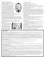
The
Dual Float
Deluxe
Dual Float
Controller
Model
Discharge
Amps
Max Solid
Max
GPM / GPH
No.
HP
Volts
Diameter
@ 10’
Handling
Head
@ 10’
S3033
1
/
3
115
1
1
/
2
”
4.0
7
/
8
”
30’
50
3000
S3050
1
/
2
115
2”
4.3
7
/
8
”
33’
65
3900
S3100
1
115
2”
11.5
1
3
/
4
”
52’
92
5520
S5033
1
/
3
115
1
1
/
2
”
4.0
1
1
/
2
”
26’
59
3540
S5050
1
/
2
115
2”
6.8
1
3
/
4
”
36’
83
4980
Specifications