8
1072_0_Product_Manual - February 24, 2011 2:52 PM
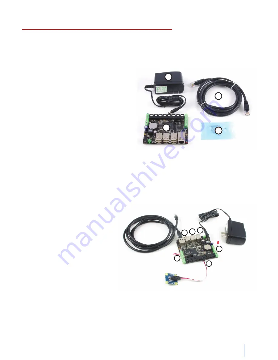
Connect the analog sensor to the analog
1.
input port 4 using a Phidgets sensor
cable. The analog input ports are
numbered from 0 to 7 starting from the
left.
Connect one end of a wire to digital
2.
input port 0 and the other end to
ground (labelled ‘G’ on the underside of
the board).
Connect the LED by inserting the long
3.
LED wire into the digital output 7 and
the shorter wire into Ground.
Connect the power supply to the
4.
PhidgetSBC2 using the barrel connector.
Connect the PhidgetSBC2 to your
5.
network with an Ethernet cable.
Plug the wall adapter into an appropriate outlet. The red status indicator light located near the USB ports should
be lit if the unit is receiving power. The green LED located above the red LED indicates boot status. The green
LED will turn on and off once during boot and then turn back on when everything is running.
Other Phidgets can also be connected to the 1072 using a USB cable.
6.
Getting Started Guide
Checking the Contents
You should have received:
A Power Supply
1.
A Cat-5e network cable
2.
A Mounting kit (4 nuts & bolts, 4 plastic spacers)
3.
A PhidgetSBC2 Board
4.
To test your new PhidgetSBC, you will also
need:
A short length of wire to test the digital inputs
•
An LED to test the digital outputs
•
An Analog Sensor to test the analog inputs
•
A UVC compatible Webcam
•
2
1
4
3
Connecting all the pieces
2
1
4
5
3
6


