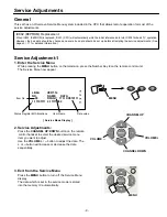
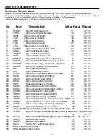
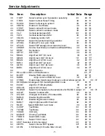
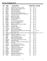
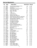
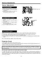
background image

-10-

-10-

Service Adjustments

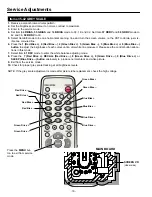
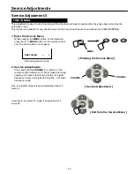
On-screen Service Menu

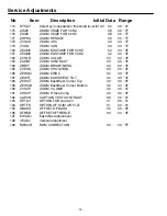
Following table shows the 

initial values

 which have been stored in the CPU ROM, and items for the service adjustments.

When  IC802  (EEPROM)  is  replaced,  check  the  bus  data  to  confirm  they  are  the  same  as  below.  The  shaded  menu  should  be 
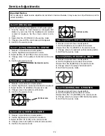
checked and be set up or readjusted according to the procedures described in the following pages.
Initial Setup Data marked with an 

 should be changed from Initial Value Data. 

No        Item          Description                          Initial Data    Range

RFAGC 

Align RF AGC threshold                                     17               00

3F

H PHA 

Align sync to fly back phase 

                        10               00

1F

VSIZE          Align vertical amplitude 

                                   72               00

7F

V DC           Align vertical DC bias                                               22               00

3F

VSIFT          Align vertical position                                               08               00

0F

V LIN   

Align vertical linearity 

                                   0F               00

1F

V SC           Align vertical S-correction                                     16               00

1F

VCOMP 

Align vertical size compensation                          07               00

07

EWDC 

Align East/West DC bias                                     33               00

3F

EWAMP 

Align East/West amplitude                                    06               00

3F

10 

EWTIL 

Align East/West Trapezoid                                    32               00

3F

11 

EWTOP 

Align East/West Top corner correction                01               00

0F

12 

EWBOT 

Align East/West Bottom corner correction 

   02               00

0F

13 

EWCSW 

Select control range for Corner correction 

   01          

  00

01

14 

HSCMP 

Align horizontal size compensation 

             07               00

07

15 

HBL             Left H-Blanking Control 

                                   04                00

07

16 

HBR             Right H-Blanking Control                                     05               00

07

17 

HPH60 

Align sync to fly back phase (60Hz data)              03               00

3F

18 

VSZ60 

Align vertical amplitude (60Hz) 

                        FF               00

FF

19 

VDC60 

Align vertical DC bias (60Hz) 

                        00               00

7F

20 

VSF60 

Align vertical position (60Hz) 

                       1D               00

1F

21 

VLI60             Align vertical linearity (60Hz) 

                        00               00

3F

22 

VSC60 

Align vertical S-correction (60Hz)                         00               00

3F

23 

VCO60 

Align vertical size compensation (60Hz)               00               00

0F

24 

EWD60 

Align East/West DC bias (60Hz)                          01               00

7F

25 

EWA60 

Align East/West amplitude (60Hz)                         7F          

  00

7F

26 

EWT60 

Align East/West trapezoid (60Hz)                         01               00

7F

27 

EWB60 

Align East/West Bottom corner correction (60Hz)  02               00

1F

28 

EWP60 

Align East/West Top corner correction (60Hz)      03               00

1F

29 

CSW60 

Select control range for Corner correction 

    00               00

01

30 

CMP60 

Align horizontal size compensation 

               03               00

0F

31 

T DIS  Disable the Test SW & enable Audio / Video Mute SW     01               00

01

32 

HFREQ 

Align ES Sample horizontal frequency (MP is adjusted in the wafer line.) 

                                                                                                                40               00

7F

33 

AFC G 

Select horizontal first loop gain & H-sync gating on/off    00  00

01

34 

AMUTE 

Disable audio outputs 

                                    00               00

01

35 

VMUTE 

Disable video outputs 

                                    00               00

01

36 

VSZ75 

Enable 75% vertical size mode                           00               00

01

37 

SKILL Force free-run mode 

                                               00        

   00

01

38 

VKILL Disable vertical mode 

                                               00               00

01

Summary of Contents for 113020208

Page 1: ...and CH01 CH13 Mid band CH14 CH22 Super band CH23 CH36 Hyper band CH37 CH64 Ultra band CH65 CH94 and CH100 CH125 Low mid band CH95 CH99 Video IF 45 75MHz Aerial Input Impedance 75Ω Input Terminals AV1 Video Composite Video Input Phone Jack x 1 S Video Input Separated Y C DIN 4 pin Jack x 1 AV1 Audio L R Stereo Input Phone Jack x 1 set AV2 Video Composite Video Input Phone Jack x 1 AV2 Audio L R Ste...

Page 2: ...e tube The picture tube is specially con structed to limit X RADIATION emissions For continued X RADIATION protection the replacement tube must be the same type as the original including suffix letter Excessive high voltage may produce potentially hazard ous X RADIATION To avoid such hazards the high voltage must be maintained within specified limit Refer to this service manual high voltage adjust...

Page 3: ...D S VIDEO C VIDEO V E 1 4 1 8 7 A L V O E D I V T U O R O T I N O M S VIDEO Y AV1 V T U O T R E V O E D I V P M 3 3 5 2 M J N AV1 AV2 DVD AUDIO IN AUDIO BUS MONITOR OUT AUDIO AUDIO L R SPEAKER L SIF OUT L R L 3 0 7 2 7 A L R E 5 0 2 2 4 A L R L R L D V D 2 V A 1 V A P F B 2 5 0 4 C T T U P N I O I D U A T U O O I D U A T U P T U O O I D U A N E K N A S V 0 2 2 C A SPEAKER R POWER LA7846NZ 28V 32V ...

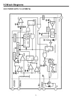
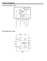
Page 4: ...IC Block Diagrams IC601 POWER SUPPLY IC STRW6754 FUNCTIONAL BLOCK DIAGRAM ...

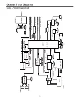
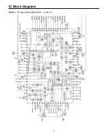
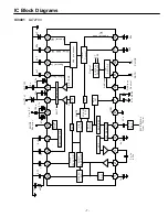
Page 5: ...IC Block Diagrams IC201 IF Video Chroma Def CPU LA76113 ...

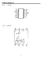
Page 6: ... IC Block Diagrams IC501 Vertical Output LA78141 IC001 AUDIO AMP LA42205 ...

Page 7: ... L R DEMOD ST SAP SW LPF 6dB PILOT CANCELLER STEREO PLL PILOT DET PILOT LEVEL DET IIC DECODE SYSTEM CONTROL Offset Cancell dbx processor SAP DET 4u7 4u7 22u 4u7 OUT L OUT R MODE Monitor 2u2 1u 1u 0 1 1u 4k7 MUTE L R L R SAP ST SAP Address Control GND MUTE Wide RMS DET Spectral DET Spectral In Offset Cancel 0 1u 0 1u 4u7 1u to 0 33u SIF SIGNAL from Tuner Address Control IIC DATA IIC CLOCK 2u2 22u S...

Page 8: ... IC Block Diagrams IC1002 NJM2533M IC1001 TC4052BF ...

Page 9: ...ce Menu Press the MENU button to turn off the Service Menu display The data which is set in the service mode is stored into the memory IC automatically Service Mode Display Service Adjustment 1 1 Enter the Service Menu While pressing the MENU button on the television press the Number Key 2 on the remote control unit The Service Menu now appear IC802 EEPROM Replacement When IC802 EEPROM is replaced...

Page 10: ...correction 01 00 01 14 HSCMP Align horizontal size compensation 07 00 07 15 HBL Left H Blanking Control 04 00 07 16 HBR Right H Blanking Control 05 00 07 17 HPH60 Align sync to fly back phase 60Hz data 03 00 3F 18 VSZ60 Align vertical amplitude 60Hz FF 00 FF 19 VDC60 Align vertical DC bias 60Hz 00 00 7F 20 VSF60 Align vertical position 60Hz 1D 00 1F 21 VLI60 Align vertical linearity 60Hz 00 00 3F ...

Page 11: ... 58 GDRV Align Green OUT AC level 38 00 7F 59 BDRV Align Blue OUT AC level 3C 00 7F 60 White Balance 00 FF 61 RD xx GD xx BD xx White Balance 00 7F 62 BLDEF Disable RGB output blanking 00 00 01 63 SUBBI Align common RGB DC level 38 00 7F 64 VTRNS Enable data transmission between vertical retrace period 01 00 01 65 DOSDSelect Analogue OSD mode Digital OSD mode 01 00 01 66 EXCNT Align Ext RGB amplit...

Page 12: ...1 104 STRSW Select sound trap ON OFF 01 00 01 105 VIFSY Select VIF Freq 38 0 38 9 39 5 45 75 58 75MHz 03 00 07 106 VLEV Align IF video level 04 00 07 107 VCOFQ Align ES Sample IF VCO Frequency MP is adjusted in the wafer line 60 00 FF 108 AMOSW Select pin 70 output 00 00 01 109 DEMTC Select De emphasis Time Constant 01 00 01 110 FMGAI Select FM Output Level 00 00 01 111 A2SW West Germany Output Le...

Page 13: ...46 CBPF Fine adjust of chroma BPF 01 00 03 147 STRAP Fine adjust of sound trap 03 00 07 148 YGAMG Select Y gamma gain 00 00 03 149 GRAY Service Test Mode White Gray 00 00 01 150 YCMIX Select YC_C Input or 2 2V_DC Input 00 00 01 151 TXTCC Select output by LPF or not 00 00 01 152 VIDEO Video signal selector 00 00 03 153 DLYTE DELAY Test 00 00 01 154 SYSEP Select sync separation threshold level 03 00...

Page 14: ... ZCONT ZOOM CONTRAST 00 00 3F 184 ZBRIT ZOOM BRIGHTNESS 00 00 3F 185 ZVPOS ZOOM V POSITION 00 00 0F 186 ZEWDC ZOOM EWDC 00 00 3F 187 ZEWTI ZOOM EAST WEST TILT 00 00 3F 188 ZEWCT ZOOM East West Corner Top 02 00 0F 189 ZEWCB ZOOM East West Corner Bottom 02 00 0F 190 ZVSCP ZOOM V COMP 00 00 07 191 ZHSCP ZOOM H Size Comp 00 00 0F 192 CAPCN CAPTION TEXT CONTRAST 06 00 07 193 OPTAV OPTION FOR AV2 AV3 01...

Page 15: ...ast to maximum 3 Select Item No 03 V DC in the service mode 4 Change value to be optimum vertical centre position 5 Exit from the service mode 1 Receive a monochrome circular pattern 2 Set the brightness and contrast to maximum 3 Select Item No 04 VSHIFT in the service mode 4 Change value to be optimum vertical centre position 5 Exit from the service mode 1 Receive a monochrome circular pattern 2 ...

Page 16: ... the brightness of each colour until a dim white line produced Please see the control button alloca tions in this mode 7 Select Item 61 DRV mode to enter the white balance adjusting mode 8 Press the 7 Red Drive RECALL Red Drive 8 Green Drive 0 Green Drive 9 Blue Drive or SLEEP Blue Drive button alternately to produce normal black and white picture 9 Exit from the service mode 10 Check for proper g...

Page 17: ...is available for one channel only and the fine tuned channel is memorized into IC802 EEPROM 1 Enter the Service Menu While pressing the MENU button on the television press the 4 or MENU button on the remote control unit The Service Menu now appear 2 Service Adjustments Press and hold the VOLUME button on the remote control handset or TV set to make fine tuning adjustment Press and hold the button ...

Page 18: ...wer supply turn the power to the TV set OFF and then ON again via either the main power switch or the ON OFF button on the remote control This will work only if the power supply trou ble was temporary If there is permanent trouble such as a damaged circuit power cannot be restored and the circuit will have to be repaired Protection Circuit HIGH VOLTAGE CHECK Note B 140V Voltage and Grayscale Adjus...

Page 19: ... FRONT 4 1AV2LA9FA01 LATCH PUSH or 1LG2LA9FA01 LATCH PUSH 5 1AA2DES0997 DEC SHEET 6 1AA2CAM0684A CABINET FRONT 7 1LG2BAA0011 BADGE PHILCO 8 1AA2CBM0484 CABINET BACK 9 1AA6P4S3560 LABEL RATING 10 1AV0U10B30304 ASSY REMOCON JXMTH 1 1AV4U19B00700 ANTENNA CONVERTER 1AV4U19B00701 ANTENNA CONVERTER 1LG6P1P0423 INSTRUCTION MANUAL BF5A Key No Part No Description Key No Part No Description 1 2 7 6 4 5 3 ...

Page 20: ...Non polarised Electrolytic OS SOLID Aluminium Solid with Organic Semiconductive Electrolytic DL ELECT Double Layered Electrolytic RESISTOR CARBON 4 7K J A 1 4W Rated Wattage Performance Symbols A General B Non flammable Z Low noise Other Temperature coefficient Tolerance Symbols A 0 05 B 0 1 C 0 25 D 0 5 F 1 G 2 J 5 K 10 M 20 P 5 15 Rated value ohms K 1 000 M 1 000 000 Material CARBON Carbon MT FI...

Page 21: ...333KGQBNG CERAMIC 0 033U K 50V C214 CEXLB1H1R0VDN ELECT 1U M 50V C215 CEXLB1HR33VDN ELECT 0 33U M 50V C216 CEXLB1C100VDN ELECT 10U M 16V C217 CK1H103KGQBNG CERAMIC 0 01U K 50V C218 CK1E473KGQBNG CERAMIC 0 047U K 25V C219 CK1H332KGQBNG CERAMIC 3300P K 50V C223 CH1H474JAGANN MT COMPO 0 47U J 50V C224 CK1H223KGQBNG CERAMIC 0 022U K 50V C225 CEXLB1C101VDN ELECT 100U M 16V C226 CK1H103KGQBNG CERAMIC 0 ...

Page 22: ... 35V C805 CEXLB1C101VDN ELECT 100U M 16V C815 CK1H103KGQBNG CERAMIC 0 01U K 50V C850 CEXLB1H100VDN ELECT 10U M 50V D001 DDXAAED0434 DIODE 1N4148 D001 DDXLBB047 N DIODE 1SS133ST D001 DDXLBB054 N DIODE 1N4448 D001 DD1SS133 N DIODE 1SS133 D004 DDXLBB053 G DIODE 1SS35 D004 DD1SS352 G DIODE 1SS352 TPH3 D004 DD1SS355 G DIODE 1SS355 TE 17 D1007 DZUDZS12B G ZENER DIODE UDZS TE 1712B D1007 DZXLBXB12B G ZEN...

Page 23: ...S133ST D614 DDXLBB054 N DIODE 1N4448 D614 DD1SS133 N DIODE 1SS133 D614 DD1S2076A N DIODE 1S2076A E D615 DDES1Z N DIODE ES1Z D615 DDXLBB041 N DIODE EU1 D616 DDEG01C N DIODE EG01C D616 DDXLBB035 N DIODE EG01C D619 DDXLBB053 G DIODE 1SS35 D619 DD1SS352 G DIODE 1SS352 TPH3 D619 DD1SS355 G DIODE 1SS355 TE 17 D621 DDRU3YX N DIODE RU3YX D621 DDXLBB038 N DIODE RU3YX D622 DDRU4AMLF J3N DIODE RU4AM LF J3 D6...

Page 24: ...202 TR 2SC1740S Q463 TXXLBB006 P TR MMBTSC3928R Q463 7T200220 TR 2SC2412K P 6 Q622 TXXLBB002 N TR CJC1815 GR Q622 T2SC1815 GR N TR 2SC1815 GR Q631 TXXLBB004 N TR CJB985 S Q631 T2SB985 S N TR 2SB985 S Q632 TXXLBB002 N TR CJC1815 GR Q632 T2SC1815 GR N TR 2SC1815 GR Q651 T2SD1347 S N TR 2SD1347 S Q652 TXXLBB005 P TR MMBTSA1235F Q652 7T210221 TR 2SA1037K P 6 Q671 T2SB985 S N TR 2SB985 S Q672 TXXLBB006...

Page 25: ...E 100 JA 1 10W R229 RGF1003JTCANL MT GLAZE 100K JA 1 10W R230 RGF1000JTCANL MT GLAZE 100 JA 1 10W R231 RDD1500JPAANN CARBON 150 JA 1 6W R232 RDD1500JPAANN CARBON 150 JA 1 6W R233 RGF1000JTCANL MT GLAZE 100 JA 1 10W R234 RGF1002JTCANL MT GLAZE 10K JA 1 10W R240 RGF1000JTCANL MT GLAZE 100 JA 1 10W R242 RGF2700JTCANL MT GLAZE 270 JA 1 10W R244 RGF2700JTCANL MT GLAZE 270 JA 1 10W R245 RGF1000JTCANL MT...

Page 26: ... RDB1003JPBANN CARBON 100K JA 1 4W R673 RDD1002JPAANN CARBON 10K JA 1 6W R676 RGF2202JTCANL MT GLAZE 22K JA 1 10W R677 RDA3901JPCANN CARBON 3 9K JA 1 2W R698 RDB1001JPBANN CARBON 1K JA 1 4W R841 RGF4701JTCANL MT GLAZE 4 7K JA 1 10W R842 RGF4701JTCANL MT GLAZE 4 7K JA 1 10W R884 RDB22R0JPBANN CARBON 22 JA 1 4W R885 RDD1501JPAANN CARBON 1 5K JA 1 6W R886 RDD2202JPAANN CARBON 22K JA 1 6W R887 RDD2202...

Page 27: ...RDA2701JPCANN CARBON 2 7K JA 1 2W R721 RGF1800JTCANL MT GLAZE 180 JA 1 10W R723 RDD4700JPAANN CARBON 470 JA 1 6W R724 RSXAV2123JDAK OXIDE MT 12KJB 2W R732 RDD10R0JPAANN CARBON 10 JA 1 6W R741 RGF1201JTCANL MT GLAZE 1 2K JA 1 10W R742 RGF5601JTCANL MT GLAZE 5 6K JA 1 10W R744 RGF5600JTCANL MT GLAZE 560 JA 1 10W R745 RGF1002JTCANL MT GLAZE 10K JA 1 10W ...

Page 28: ...Feb 2009 ...

Page 29: ...C RC ON OFF P F STB ON OFF ON OFF R G B R G B S MUTE ONTIMER ONTIMER 8V 5V_IF 5V_IF 1 2DJ330 R475 T471H10 1 10GJ1KC R432 1600MJ 8000LBYC C423 1 2 Q432AH1 2SC3332S Q431 2SC3332R CL60 1K R424 250EM334V C486 X R436 CL57 J R466 L462H2 T471H9 L442H2 180K R470 T471H7 CL50 DJ47K R422 1 2DJ1K R433 T471H2 L26B0170N L461 B4L26B0030N CL61 B4L26B1290N L442 CL43 CL49 CL62 250GJ0 47 C437 DZXLBZA5 1B D476 1600MJ...

Page 30: ...D611 C1111 C611 C011 R1112 D612 C3412 C1112 C612 C212 C012 R613 C3413 C1913 C613 C013 R1114 C3414 C614 C214 C615 C215 D616 C3416 C616 C216 C617 R618 C3418 C618 R619 C619 R620 C3420 Q461A Q432A 1 F601A D1901A D621 C3421 C1021 R422 E Q622 F601B C3422 C1022 C622 C3423 C1023 C223 D624 C3424 C225 C627 R628 C628 R629 C629 C229 T431 R631 E Q631 E Q431 L631 L431 D1902A R632 E Q632 L432 C632 C432 C232 R433...

Reviews: