-12-
-12-
Service Adjustments
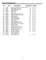
No Item Description Initial Data Range
84
CKOFF
Disable Killer circuit (for IC Test) 00
00
~
01
85
CKOPE
Select color killer operational level
04
00
~
07
86
AUTOG
Adjust Auto Green level
00
00
~
07
87
TINTT Set tint center value
01*
00
~
01
88
WBADJ
Auto correct black level
00
00
~
01
89
IDKIL Select color ident operational level
04
00
~
07
90
CVCOA
Control free Run frequency of chroma VCO 04
00
~
07
91
CVCOC
VCO free run mode 00
00
~
01
92
FSCSP
Select 10 pin output 01
00
~
01
93
COLSY
Select Color System
05*
00
~
07
94
RBGAI
R-Y/B-Y Gain Balance
07
00
~
0F
95
RBANG
R-Y/B-Y Angle
05
00
~
0F
96
RYLEV
R-Y DC Level (White-Balance)
07
00
~
1
F
97
BYLEV
B-Y DC level (White-Balance)
08
00
~
1
F
98
GYAMP
Adjust G-Y amplitude
08
00
~
0F
99
HTNCL
Select color on/off at Half Tone Mode
00
00
~
01
100 VXOFR
VXO test mode
00
00
~
01
101 VXOSB
VXO test mode
00
00
~
01
102 IFAGC
Disable IF and RF AGC 00
00
~
01
103 SVOSW
Select pin 68 output 00
00
~
01
104 STRSW
Select sound trap ON/OFF 01
00
~
01
105 VIFSY
Select VIF Freq. 38.0/38.9/39.5/45.75/58.75MHz
03
00
~
07
106 VLEV Align IF video level 04
00
~
07
107 VCOFQ Align ES Sample IF VCO Frequency. (MP is adjusted in the wafer line) 60 00
~
FF
108 AMOSW
Select pin 70 output 00
00
~
01
109 DEMTC
Select De-emphasis Time Constant
01
00
~
01
110
FMGAI
Select FM Output Level
00
00
~
01
111
A2SW West Germany Output Level
00
00
~
01
112
SIFSY Select 4.5/5.5/6.0/6.5 MHz 00
00
~
03
113
CHCON
CH converter measure mode at India
00
00
~
01
114
FMMUT
Disable FM output 00
00
~
01
115
AFTSE
Select AFT sensitivity 10/13/20/40 [mV/KHz] 02
00
~
03
116
IFTES IF Test mode 00
00
~
01
117
VCOAD
Fine adjust of IFVCO Free run
08
00
~
0F
118
EWTES
Select East/West DAC test mode 00
00
~
07
119
VOLFL
Enable volume filter 01
00
~
01
120 VOL L Customer L-ch volume control
7F
00
~
7F
121 AUDSW
Select audio input signal 00*
00
~
03
122 CLKTS
Operation CLK test modes 02
00
~
03
123 SRCNT
Select surround effect
00*
00
~
03
124 DCCUT
DC cut test modes 02
00
~
03
125 MONOM
Enable mono input mode 00
00
~
01
126 VOL R Customer R-ch volume control
7F
00
~
7F
127 TOATT
Enable tone attenuator
00
00
~
01
Summary of Contents for 113020208
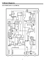
Page 4: ...IC Block Diagrams IC601 POWER SUPPLY IC STRW6754 FUNCTIONAL BLOCK DIAGRAM ...
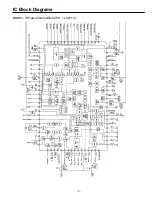
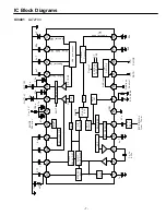
Page 5: ...IC Block Diagrams IC201 IF Video Chroma Def CPU LA76113 ...
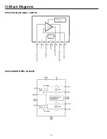
Page 6: ... IC Block Diagrams IC501 Vertical Output LA78141 IC001 AUDIO AMP LA42205 ...
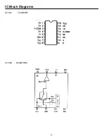
Page 8: ... IC Block Diagrams IC1002 NJM2533M IC1001 TC4052BF ...
Page 28: ...Feb 2009 ...


