-18-
-18-
Service Adjustments
Service Adjustment-4
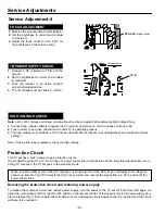
FOCUS ADJUSTMENT
1.
Receive the monochrome circular pattern.
2.
Set the brightness to normal and contrast
to maximum.
3.
Adjust the focus control on the F.B.T. for
the best focus on the screen centre.
FOCUS VR
(Upper side)
This TV set has a built-in power supply protection circuit.
It is provided to protect the TV set in case of a power supply circuit malfunctions. When something abnormality occurs
during TV reception, the TV set goes to the stand-by mode.
When an abnormality occurs during TV reception, it causes pin 23 of the CPU to go continually Low voltage for
about one second. The CPU detects that this has occurred and outputs the signal from pin 36 to switch off the
power supply lines.
Releasing the protective circuit and restoring power supply
To release the protective circuit and restore power supply, turn the power to the TV set OFF and then ON again via
either the main power switch or the ON-OFF button on the remote control. This will work only if the power supply trou-
ble was temporary. If there is permanent trouble such as a damaged circuit, power cannot be restored and the circuit
will have to be repaired.
Protection Circuit
HIGH VOLTAGE CHECK
Note:
+B (+140V) Voltage and Grayscale Adjustment must be completed before attempting High Voltage Check.
1.
Connect high voltage voltmeter negative lead to ground, and c lead to anode of picture tube.
2.
Tune receiver to an active channel and confirm TV is operating properly.
3.
The high voltage must be 28KV ± 1KV and less than 29.5KV at 0 beam current (Brightness and contrast minimum
setting).
Note: If the picture tube is replaced, check the high voltage.
+B POWER SUPPLY CHECK
1.
Connect a DC voltmeter to TP-B and the
ground.
2.
Set the brightness to normal and contrast
to maximum.
3.
Tune the receiver to an active channel
and synchronized picture.
4.
The +B voltage must be 140± 2.0 volt DC.
TP-B
Summary of Contents for 113020208
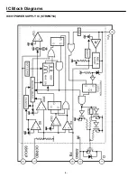
Page 4: ...IC Block Diagrams IC601 POWER SUPPLY IC STRW6754 FUNCTIONAL BLOCK DIAGRAM ...
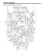
Page 5: ...IC Block Diagrams IC201 IF Video Chroma Def CPU LA76113 ...
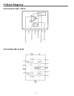
Page 6: ... IC Block Diagrams IC501 Vertical Output LA78141 IC001 AUDIO AMP LA42205 ...
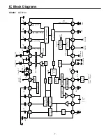
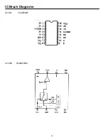
Page 8: ... IC Block Diagrams IC1002 NJM2533M IC1001 TC4052BF ...
Page 28: ...Feb 2009 ...

